

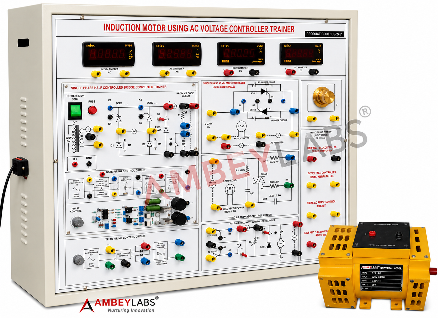
AL-E742 UNIVERSAL MOTOR CONTROL USING AC-DC CONTROLLER (SCR, TRIAC BASED)
Project Information
- Category: ELECTRICAL ENGINEERING
- Sub Category: POWER ELECTRONICS AND DRIVE LAB
- Model Number: AL-E742
Description
AL-E742
UNIVERSAL MOTOR CONTROL USING AC-DC VOLTAGE CONTROLLER USING SCR, TRIAC TRAINER
·
DETAILED TECHNICAL SPECIFICATIONS
·
AL-E742 – Universal Motor Control Using AC-DC Controller (SCR &
TRIAC Based)
·
MODEL NO: AL-E742
- Overview
·
The AL-E742 Universal Motor Control Using AC-DC Controller Trainer is a
comprehensive laboratory trainer designed to study the speed control
characteristics of a Universal Motor using various SCR and TRIAC based AC/DC
power electronic converters. The trainer enables students to perform practical
experiments on AC voltage controllers and controlled rectifiers, understand
phase angle control techniques, analyze motor performance under different
firing angles, and observe voltage/current waveforms using an oscilloscope.
·
The equipment is suitable for diploma, undergraduate, postgraduate
engineering laboratories, technical institutes, and industrial training
centers.
2. Learning Objectives
·
The trainer shall enable students to perform the following experiments:
·
Speed Control of Universal Motor using Anti-Parallel SCR AC Voltage
Controller
·
Speed Control using TRIAC AC Voltage Controller
·
Speed Control using Single Phase Half Controlled Rectifier
·
Speed Control using Single Phase Fully Controlled Rectifier
·
Speed Control using Half Controlled Bridge Converter
·
Speed Control using Fully Controlled Bridge Converter
·
Study of AC Phase Angle Control Technique
·
Observation of Trigger Pulse Generation
·
Measurement of Input and Output Voltage
·
Measurement of Motor Current
·
Study of Speed versus Firing Angle Characteristics
·
Analysis of Torque-Speed Characteristics
·
Observation of AC and DC Waveforms
·
Study of Power Electronics Switching Devices
·
Study of Snubber Circuit Performance
3.
Technical Specifications
·
Power Supply
·
Input Supply : 230 V AC ±10%, 50 Hz
·
Built-in Regulated DC Supply : +15 V DC, 150 mA
·
Isolated Variable AC Supply : 0–220 V AC, 2 A
·
Protected against overload and short circuit
Power
Devices
·
The trainer shall incorporate:
·
SCR (TYN604 or equivalent)
·
TRIAC (BT136 or equivalent)
·
RC Snubber Circuit
·
Gate Driver Circuit
·
AC Phase Control Circuit
·
TRIAC Trigger Circuit
·
Universal Motor
·
Rating : 0.5 HP
·
Supply : Single Phase AC
·
Suitable for AC & DC Operation
·
Mounted securely on trainer base
·
Coupled with protective enclosure
Converter
Configurations
·
The trainer shall provide separate experimental configurations for:
·
Anti-Parallel SCR AC Voltage Controller
·
TRIAC AC Voltage Controller
·
Half Controlled Rectifier
·
Fully Controlled Rectifier
·
Half Controlled Bridge Converter
·
Fully Controlled Bridge Converter
·
Each circuit shall be individually accessible through safety sockets.
Gate
Triggering Circuit
·
Phase Angle Control Technique
·
Adjustable firing angle
·
Stable triggering over full control range
·
Electrical isolation between control and power circuits
·
Trigger pulse test points
Measurement
Instruments
·
Digital AC Voltmeter
·
Range : 0–200 V AC
·
Resolution : 0.1 V
·
Accuracy : ±1%
·
Digital AC Ammeter
·
Range : 0–2 A
·
Resolution : 0.01 A
·
Digital DC Voltmeter
·
Range : 0–200 V DC
·
Resolution : 0.1 V
·
Digital DC Ammeter
·
Range : 0–2 A
·
Resolution : 0.01 A
Load
Arrangement
·
0.5 HP Universal Motor
·
Lamp Load for demonstration
·
Inductive load experimentation
4.
Test Points
·
Adequate test points shall be provided for measuring:
·
Input AC Voltage
·
Output Voltage
·
Trigger Pulses
·
SCR Gate Pulses
·
TRIAC Gate Pulses
·
Motor Voltage
·
Motor Current
·
Reference Ground
·
All high-voltage terminals shall use 4 mm safety sockets.
Oscilloscope
Interface
·
The trainer shall provide:
·
10:1 Potential Divider
·
CRO Measurement Points
·
Waveform Observation Terminals
·
Trigger Pulse Observation
·
Output Voltage Waveform Observation
·
Load Voltage Observation
6.
Protection Features
·
The trainer shall include:
·
Input MCB/Fuse Protection
·
Output Fuse Protection
·
Snubber Protection Circuit
·
Shock-Proof Metal Cabinet
·
Safety Earth Terminal
·
Insulated Front Panel
·
Safety Banana Sockets
·
Overload Protection
7.
Front Panel
·
The front panel shall be manufactured using:
·
Industrial grade FRP/PCB insulated panel
·
Silk-screen printed circuit diagram
·
Clearly marked symbols
·
Component identification
·
Functional block layout
·
Color coded sockets
8.
Construction
·
Heavy-duty powder coated metal cabinet
·
Bench-top model
·
Approximate Size : 24" × 20"
·
Rubber feet for stability
·
Proper ventilation
9.
Accessories Supplied
·
The trainer shall be supplied complete with:
·
2 mm Patch Cords
·
4 mm Patch Cords
·
Power Cord
·
User Manual
·
Experiment Manual
·
Circuit Diagrams
·
List of Experiments
10.
Optional Accessories
·
Dual Channel Digital Storage Oscilloscope (DSO/CRO)
·
Clamp Meter
·
Isolation Transformer
11.
Experiments Included
·
Study of Universal Motor Characteristics
·
Speed Control using Anti-Parallel SCR
·
Speed Control using TRIAC
·
Half Wave Controlled Rectifier Operation
·
Fully Controlled Rectifier Operation
·
Half Controlled Bridge Converter
·
Fully Controlled Bridge Converter
·
Phase Angle Control using SCR
·
Phase Angle Control using TRIAC
·
Observation of Trigger Pulses
·
Output Voltage Waveform Analysis
·
Motor Speed versus Firing Angle
·
Motor Current Measurement
·
AC Voltage Controller Characteristics
·
Effect of Snubber Circuit
·
Performance Comparison of SCR and TRIAC Controllers
12.
Educational Outcomes
·
After performing the experiments, students will be able to:
·
Understand the operation of Universal Motors.
·
Study SCR and TRIAC switching characteristics.
·
Learn AC voltage control techniques.
·
Understand controlled rectifier operation.
·
Analyze phase angle control methods.
·
Measure electrical parameters using digital instruments.
·
Observe triggering waveforms.
·
Compare different converter topologies.
·
Understand speed control of AC/DC motors.
·
Gain practical knowledge of industrial motor control systems.
13.
Standard Supply
·
Universal Motor Control Trainer
·
Built-in Power Supplies
·
Digital Measuring Instruments
·
Universal Motor Assembly
·
Patch Cords (2 mm & 4 mm)
·
Experiment Manual
·
User Manual
·
Power Cable
Compliance
·
The trainer shall be factory assembled, fully wired, tested, and ready
for operation. It shall conform to standard laboratory safety practices and be
suitable for engineering colleges, polytechnics, vocational institutes, and
industrial training laboratories. The specifications are based on the uploaded
product document.