

AL-1405 STUDY OF EARTH AND RESIDUAL CURRENT CIRCUIT BREAKER
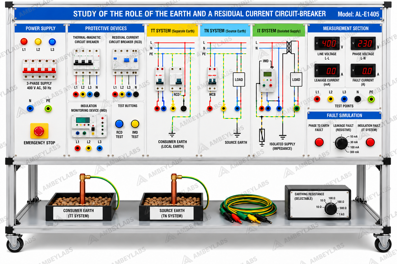
Project Information
- Category: ELECTRICAL ENGINEERING
- Sub Category: ELECTRICAL ENGINEERING
- Model Number: AL-1405
Description
AL-1405
STUDY OF EARTH AND RESIDUAL CURRENT CIRCUIT BREAKER
Reference:
AL-E1405
The equipment shall be an educational
training module designed for practical study of electrical hazards, protective
earthing, residual-current protection and fault-current paths in low-voltage
electrical installations.
1. Main Requirements
|
Parameter |
Required
Specification |
|
Equipment |
Educational
Earthing & RCD Training Module |
|
Reference |
AL-E1405 |
|
Application |
Study of
protective earthing and residual-current protection |
|
Earthing Systems |
TT, TN and IT |
|
Protection Devices |
Thermal-magnetic
circuit breaker and RCD |
|
Insulation
Protection |
Insulation
Monitoring Device (IMD), where applicable |
|
Fault Study |
Controlled and
safe fault simulation |
|
Standard |
NF C 15-100
principles |
|
Training Mode |
Practical
demonstrations, measurements and exercises |
|
Safety |
Protected
terminals and controlled fault circuits |
2. Educational Objectives
The system shall enable students to:
- Understand
electrical hazards qualitatively and quantitatively.
- Understand the
role of the earth/protective conductor.
- Identify
characteristics of TT, TN and IT earthing systems.
- Understand the
purpose and operation of a residual-current circuit breaker/RCD.
- Understand the
function of thermal-magnetic circuit breakers.
- Understand
insulation monitoring and its application in IT systems.
- Trace
fault-current paths safely.
- Observe the
response of protective devices to earth/leakage faults.
- Apply relevant
NF C 15-100 protection principles.
3. Practical Experiments
The equipment shall permit practical
study of:
- Electrical
hazards and protection.
- Protective
earthing arrangements.
- TT earthing
system.
- TN earthing
system.
- IT earthing
system.
- Earth-fault
current paths.
- Operation of
thermal-magnetic protection.
- Operation of an
RCD/residual-current circuit breaker.
- Leakage/residual-current
measurement.
- Controlled
earth-fault simulation.
- Protective-device
operation and automatic disconnection.
- Comparison of
different earthing arrangements.
4. Measurement & Test Facilities
Suitable test points and/or
instruments shall permit observation/measurement of:
- Supply voltage.
- Fault voltage.
- Fault current.
- Residual/leakage
current.
- Protective
conductor current.
- Earth-related
parameters.
- Insulation
condition, where applicable.
- RCD operating
response.
5. Safety
The module shall include:
- Safe, insulated
connection terminals.
- Overcurrent
protection.
- RCD protection.
- Protective
earthing.
- Controlled
fault-generation circuitry.
- Emergency
isolation/safety facility.
- Clearly marked
test points and controls.
- Warning labels.
- Protection
against direct access to hazardous live parts.
6. Supply & Documentation
The supplier shall provide:
- Complete
training module.
- Required
protection devices.
- Earthing and
connection accessories.
- Test leads/patch
cords.
- Circuit and
connection diagrams.
- Teaching
manual.
- Practical
exercise manual.
- Safety
instructions.
- Manufacturer's
technical datasheet.
7. Supplier Confirmation
Supplier shall confirm:
- Exact
manufacturer and model.
- Catalogue or
custom-built status.
- Point-by-point
compliance.
- Complete BOM
and accessories.
- Dimensions and
weight.
- Required
utilities.
- Electrical/mechanical
interfaces.
- General
arrangement and circuit drawings.
- Safety
certificates/declarations.
- Capacity and
test evidence.
- Delivery and installation
schedule.
- Site-support
schedule.
- Warranty.
All assumptions, exclusions and deviations.