

AL-E767 – SINGLE AND THREE PHASE INVERTER 1.5KW
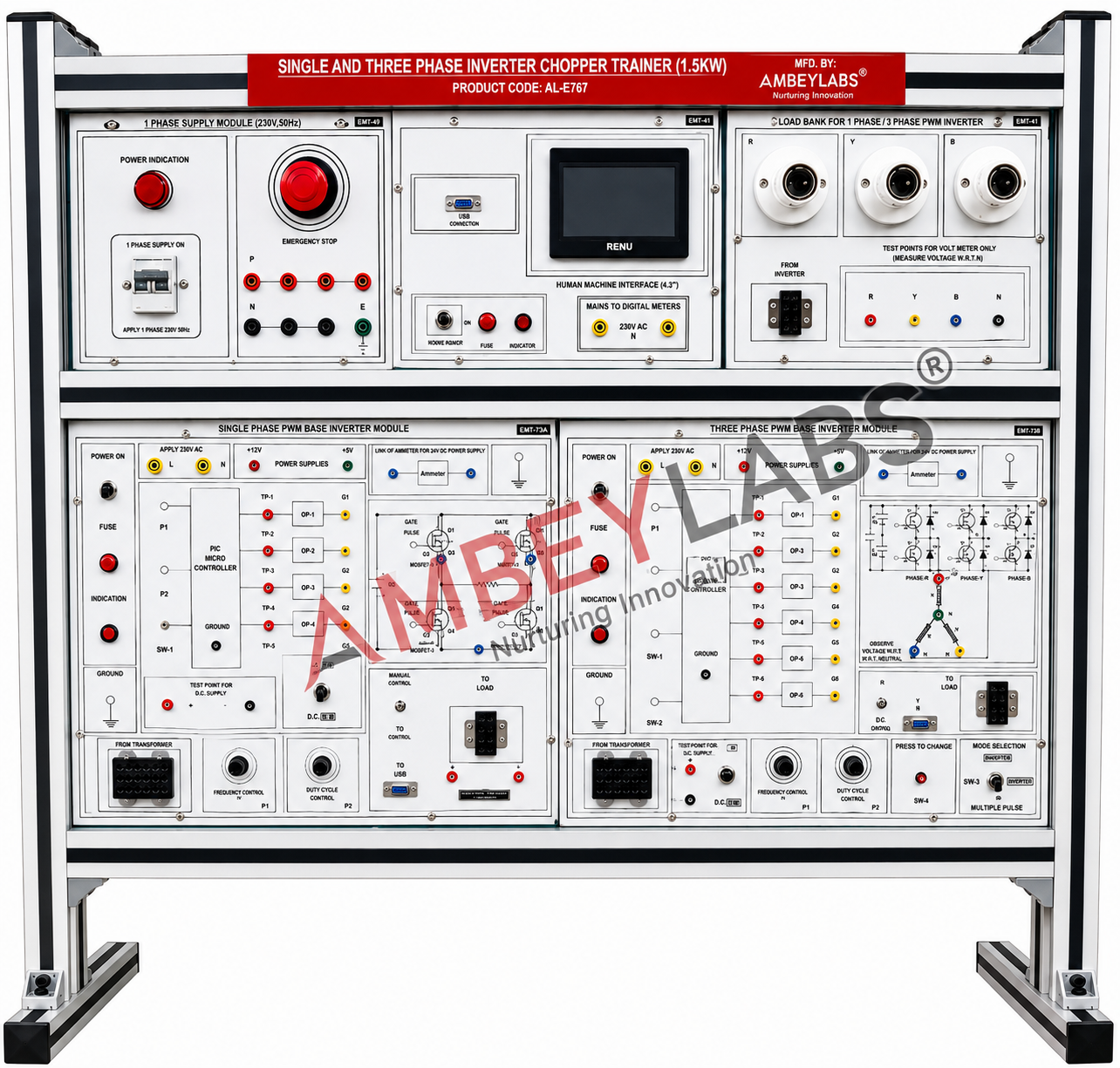
Project Information
- Category: ELECTRICAL ENGINEERING
- Sub Category: POWER ELECTRONICS AND DRIVE LAB
- Model Number: AL-E767
Description
AL-E767 SINGLE
AND THREE PHASE INVERTER 1.5KW
DETAILED TECHNICAL SPECIFICATIONS
AL-E767 – Single and Three Phase Inverter &
Chopper Trainer (1.5 kW)
Product Code: AL-E767A
Product Name: Single & Three Phase Inverter Trainer
(1.5 kW)
Category: Power Electronics Laboratory Trainer / Electrical Engineering Trainer
The AL-E767 Single and
Three Phase Inverter & Chopper Trainer is a comprehensive laboratory
training system designed for practical experimentation on power electronic
converters using PWM techniques. The trainer enables students to study the
construction, operation, testing, and performance characteristics of
single-phase and three-phase MOSFET-based inverters, along with four-quadrant
chopper operation. The modular design allows easy troubleshooting and
experimentation with industrial-standard power electronic circuits.
2. Scope of Learning
The trainer shall enable students to perform the
following experiments:
- Study of Single
Phase PWM Inverter.
- Study of Three Phase
PWM Inverter.
- Study of PWM
generation using Triangular Comparator Method.
- Study of MOSFET
switching characteristics.
- Study of PWM
frequency variation.
- Study of Duty Cycle
variation.
- Study of Single
Phase Full Bridge Inverter.
- Study of Three Phase
Bridge Inverter.
- Study of Four
Quadrant Chopper.
- Observation of
output waveforms under various load conditions.
- Harmonic analysis of
PWM inverter output.
- Measurement of
voltage, current and switching waveforms.
- Performance
evaluation with lamp load.
- Fault diagnosis and
troubleshooting of inverter circuits.
3. Technical Specifications
|
Parameter |
Specification |
|
Product Code |
AL-E767 |
|
System Type |
Single & Three
Phase Inverter and Chopper Trainer |
|
Rated Output Power |
1.5 kW |
|
Power Device |
MOSFET |
|
MOSFET Rating |
1200V, 25A |
|
PWM Generation |
Triangular Comparator
Method |
|
PWM Frequency |
Approximately 270 Hz to
5 kHz |
|
Duty Cycle Control |
0–90% and 0–50% |
|
Input Supply |
230V AC ±10%, 50/60 Hz |
|
Transformer |
Centre Tapped 230V, 1.5
kW |
|
Protection |
Single Phase 10A MCB |
|
Interconnections |
2mm & 4mm Safety
Sockets |
|
Load |
Three 200W Lamp Loads |
|
HMI Display |
4.3-inch Touch Screen |
|
Emergency Stop |
Mushroom Type Push
Button |
|
Indicators |
LED Power Indicators |
|
Cooling |
Natural Air Cooling |
|
Cabinet |
Powder-coated Metal
Cabinet |
4. Functional Modules
The trainer shall consist of the following
independent modules:
A. Human Machine Interface (HMI)
- 4.3" Industrial
Touch Screen HMI
- System parameter
display
- PWM parameter
adjustment
- User-friendly graphical
interface
- Real-time monitoring
B. Single Phase PWM Inverter Module
- MOSFET Full Bridge
configuration
- PWM gate driver
circuit
- Isolated gate pulse
generation
- Variable duty cycle
- Variable frequency
control
- Test points for
waveform observation
C. Three Phase PWM Inverter Module
- Three Phase Bridge
Inverter
- Six MOSFET switching
devices
- 120° gate pulse
generation
- PWM modulation
- Three phase output
terminals
- Load connection
terminals
D. Single Phase Chopper Module
- Four Quadrant
Chopper
- PWM control
- MOSFET switching
- Forward and Reverse
operation
- Frequency control
- Duty cycle
adjustment
E. Power Supply Module
- Single Phase AC
Input
- Isolated DC Supply
- Low voltage
auxiliary supply
- Protection circuitry
- Indicator lamps
F. Load Module
- Three Nos. 200W Lamp
Load
- Load terminals
- Test terminals
- Output measurement
points
5. Protection Features
The trainer shall include:
- Single Phase MCB
Protection
- Short Circuit
Protection
- Fuse Protection
- Emergency Stop
Switch
- Reverse Polarity
Protection
- RC Snubber Circuit
- Over Current
Protection
- Power ON Indication
- Safe Low Voltage
Control Circuit
- Industrial Safety
Sockets
6. Front Panel Features
- Industrial printed
synoptic diagram
- Printed circuit
representation
- Clearly identified
terminals
- Colour coded safety
sockets
- Test points at each
functional block
- Banana socket
interconnections
- Modular plug-in
cards
- Industrial labeling
7. Measurement Facilities
The trainer shall provide test points for
measuring:
- PWM Pulse
- Gate Signal
- DC Input Voltage
- AC Output Voltage
- MOSFET Gate Pulse
- Driver Output
- Load Voltage
- Load Current
- Frequency
- Duty Cycle
using a CRO or Digital
Storage Oscilloscope.
8. Educational Experiments
The equipment shall facilitate the following
experiments:
- Study of PWM
Generation.
- Single Phase PWM
Inverter.
- Three Phase PWM
Inverter.
- Frequency Variation.
- Duty Cycle
Variation.
- Output Voltage
Control.
- Harmonic Reduction
using PWM.
- MOSFET Switching
Characteristics.
- Four Quadrant
Chopper.
- Forward Motoring.
- Reverse Motoring.
- Regenerative
Braking.
- Dynamic Braking.
- Lamp Load
Characteristics.
- Gate Driver Circuit
Testing.
- RC Snubber Circuit
Analysis.
- Fault Diagnosis.
9. Construction
- Heavy-duty
powder-coated MS cabinet
- Aluminium/Bakelite
front panel
- Industrial-grade switches
- Gold-plated safety
sockets
- Modular PCB
construction
- Easily replaceable
power and firing modules
- Industrial wiring
harness
- Laboratory-grade
finish
10. Standard Accessories
- Power Pack
- Patch Cords (2mm
& 4mm, 1 metre)
- 3 × 200W Lamps
- Instruction Manual
- Experiment Manual
- Power Cord
- Test Leads
11. Utilities Required
- 230V AC, 50 Hz
Single Phase Supply
- Earthing Connection
- Digital Multimeter
- CRO / Digital
Storage Oscilloscope (Recommended)
12. Standard Compliance
The trainer should conform to:
- IEC Safety Standards
- Laboratory Safety
Requirements
- Industrial Wiring
Practices
- Educational
Laboratory Equipment Standards
13. Salient Features
- Industrial modular
design
- MOSFET-based 1.5 kW
power stage
- 4.3" Touch
Screen HMI
- PWM generation using
Triangular Comparator Method
- Variable frequency
and duty cycle
- Single & Three
Phase inverter operation
- Four Quadrant
Chopper operation
- Industrial safety
features
- Modular replaceable
cards
- Clearly marked test
points
- Comprehensive
laboratory experiments
- Suitable for
Diploma, Polytechnic, Engineering Colleges, Universities, and Industrial
Training Institutes.