

AL-E692B BLDC MOTOR CONTROL TRAINER WITH GUI INTERFACE 400W
Project Information
- Category: ROBOTICS AND MECHATRONICS
- Sub Category: PLC TRAINER
- Model Number: AL-E692B
Description
AL-E692B BLDC
MOTOR CONTROL TRAINER WITH GUI INTERFACE 400W
AL-E692B – BLDC Motor with Control
Trainer
Product Code: AL-E692B
Product
Category: Electrical Machines and Motor Control Training Equipment
1. Product Overview
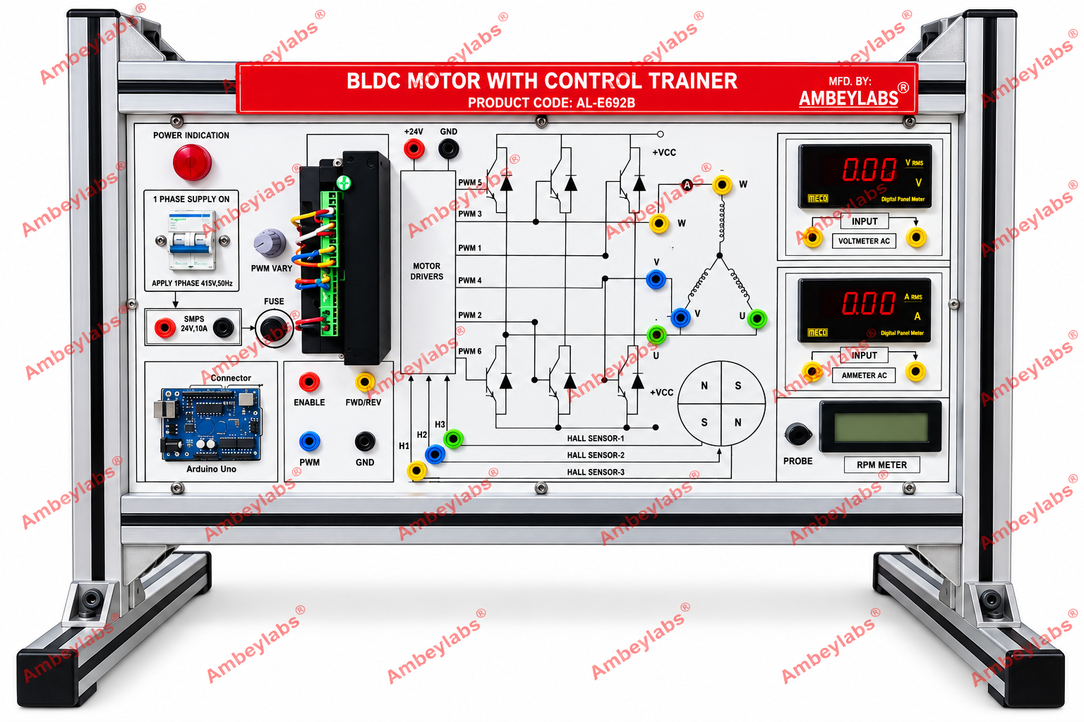
The AL-E692B BLDC Motor with Control
Trainer is an educational training system designed to demonstrate the operating
principles, electronic commutation, speed control, direction control, and
performance measurement of a Brushless DC (BLDC) motor. The trainer
incorporates a motor driver circuit, PWM control interface, Hall sensor
feedback connections, digital voltage and current meters, and an RPM
measurement facility.
The system is mounted on a rigid aluminum-profile
frame with a front-facing instructional panel, clearly identified test points,
and circuit diagrams for practical learning.
2. Detailed Technical Specifications
|
S. No. |
Parameter |
Technical Specification |
|
1 |
Product
Name |
BLDC Motor with Control Trainer |
|
2 |
Model
Number |
AL-E692B |
|
3 |
Brand |
Ambeylabs® |
|
4 |
Machine
Type |
Brushless DC Motor |
|
5 |
Motor
Control |
Electronic commutation using a motor
driver |
|
6 |
Power
Supply Section |
Single-phase supply input, as
indicated on the panel |
|
7 |
DC Power
Supply |
SMPS, 24 V, 10 A, as indicated |
|
8 |
Motor
Driver |
Electronic three-phase motor driver
circuit |
|
9 |
Switching
Control |
PWM-based motor speed control |
|
10 |
PWM
Control |
Variable PWM control provided |
|
11 |
Direction
Control |
Forward/Reverse control |
|
12 |
Motor
Enable |
Dedicated enable input |
|
13 |
Feedback
System |
Hall sensor feedback |
|
14 |
Hall
Sensor Inputs |
Three Hall sensor signal connections |
|
15 |
Controller
Interface |
Arduino Uno interface board, as shown |
|
16 |
Voltage
Measurement |
Digital AC voltmeter |
|
17 |
Current
Measurement |
Digital AC ammeter |
|
18 |
Speed
Measurement |
RPM meter with probe connection |
|
19 |
Test
Connections |
Color-coded 4 mm banana-type
terminals, as shown |
|
20 |
Protection |
Fuse provided in the power/control
circuit |
|
21 |
Frame
Construction |
Aluminum-profile support structure |
|
22 |
Front
Panel |
Printed instructional panel with
circuit diagrams and connection points |
|
23 |
Mounting |
Bench-mounted trainer with supporting
feet |
|
24 |
Intended
Application |
Electrical engineering laboratories
and motor-control training |
Note: Ratings and features above are
based on the supplied product image. Motor rated power, rated speed, exact
meter ranges, and controller specifications were not legible or explicitly
stated.
3. Main Sections and Features
A. Power Supply Section
- Single-phase AC supply input
provision, as labeled on the panel.
- Switched supply indication using a
power indicator.
- 24 V, 10 A switched-mode power supply
(SMPS), as indicated.
- Fuse protection for the relevant
circuit.
- Clearly identified supply connections
for laboratory use.
B. BLDC Motor Driver Section
- Electronic driver circuitry for
controlling the BLDC motor.
- Three-phase switching arrangement for energizing
the motor windings.
- PWM input connections for controlling
switching duty cycle.
- Motor enable input for activating or
disabling the drive.
- Forward/Reverse input for
direction-control demonstrations.
- Clearly marked motor-driver and
control-signal connections.
C. PWM Control Section
- Variable PWM control for studying
motor-speed variation.
- Dedicated PWM signal terminal.
- Ground reference terminal.
- PWM signal connections identified on
the panel.
- Provision to investigate the effect of
duty cycle on motor response.
D. Hall Sensor Feedback Section
- Three Hall sensor signal inputs
identified as Hall Sensor 1, Hall Sensor 2, and Hall Sensor 3.
- Sensor supply and ground reference
connections, as indicated.
- Provision for observing rotor-position
feedback signals.
- Demonstration of electronic
commutation based on rotor-position information.
E. Controller Interface
- Arduino Uno interface board mounted on
the front panel.
- Connector provision for
controller-based experimentation.
- Support for studying PWM generation and
digital control signals.
- Interface for examining
direction-control and motor-enable logic, subject to the implemented
controller program.
F. Measurement Section
·
Digital Voltage Meter
Digital display for voltage measurement
through the provided input terminals. The exact measurement range and whether
the instrument is configured for AC or DC measurement should be confirmed from
the meter specification.
·
Digital Current Meter
Digital current display with input
terminals for measuring current through the designated measurement circuit. The
exact range and measurement method should be verified.
·
RPM Meter
Speed measurement unit with a probe
connection for demonstrating motor rotational speed. The sensor type and
measurable RPM range are to be confirmed.
4. Experiments and Learning Objectives
The trainer is suitable for the
following experiments:
- Study of BLDC motor construction and
operating principles.
- Identification of the motor driver,
controller, and feedback connections.
- Study of electronic commutation in a
BLDC motor.
- Speed control using pulse-width
modulation (PWM).
- Study of the relationship between PWM
duty cycle and motor speed.
- Forward and reverse direction control.
- Studies of the motor enable function.
- Observation of Hall sensor feedback
signals.
- Study of rotor-position detection
using three Hall sensors.
- Measurement of motor speed using the
RPM meter.
- Study of motor voltage and current
under different operating conditions.
- Understanding the role of the
electronic driver in energizing the motor phases.
- Introduction to microcontroller-based
motor control using an Arduino-compatible interface.
- Troubleshooting of motor-control and
feedback signal connections.
5. Working Principle
A Brushless DC motor uses electronic
switching instead of mechanical brushes and a commentator. The electronic
driver energizes the motor phases in a sequence that produces a rotating
magnetic field. The permanent-magnet rotor follows this field and generates
mechanical rotation.
Hall sensors detect rotor position and
provide feedback to the controller. The controller uses this information to
determine the appropriate switching sequence for the motor phases.
Motor speed can be adjusted by changing
the PWM duty cycle supplied to the driver. The forward/reverse input changes
the phase-commutation sequence to reverse the direction of rotation, provided
the motor driver and control program support this function.
6. Mechanical Construction
- Rigid aluminum-profile frame.
- Bench-mounted construction with
supporting feet.
- Front-mounted panel with printed
circuit diagrams and terminal labels.
- Color-coded terminals for easy
identification of control and measurement connections.
- Clearly separated power, driver,
feedback, and measurement sections.
- Components arranged for convenient
laboratory access and demonstration.
7. Safety and Operating Requirements
- Operate the trainer using the supply
ratings confirmed by the manufacturer.
- Verify the AC input requirement before
connecting the supply; the image's supply label should be checked against
the actual unit.
- Ensure correct motor phase, Hall
sensor, and controller connections before energizing the system.
- Use appropriate fuse protection and
electrical safety procedures.
- Do not change motor wiring while the
system is powered.
- Keep rotating motor parts guarded
during operation.
- Use the trainer under qualified
laboratory supervision.
OPTIONAL
ACCESSORIES:
· PC/LAPTOP (Not provided with trainer kit)