

AL-E500D ANTENNA MEASUREMENT SYSTEM / ANTENNA TRAINER (MOTORISED AND PLOTTING SOFTWARE)
Project Information
- Category: ELECTRONICS ENGINEERING
- Sub Category: ADVANCE COMMUNICATIONS
- Model Number: AL-E500D
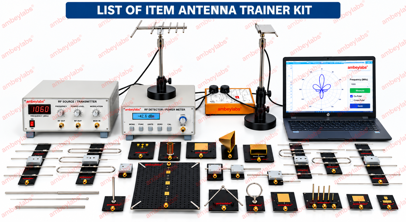
Description
AL-E500D ANTENNA MEASUREMENT SYSTEM / ANTENNA TRAINER
(MOTORISED
AND PLOTTING SOFTWARE)
ANTENNA
MEASUREMENT SYSTEM / ANTENNA TRAINER
Detailed Technical Specifications
1. RF Source
|
Parameter |
Specification |
|
Source Type |
PLL Synthesized RF source with integrated VCO |
|
Frequency Range – MIC Source |
2 GHz to 3 GHz |
|
Frequency Range – Antenna Transmitter |
500 to 950 MHz |
|
Frequency Resolution |
1 MHz |
|
Minimum Transmitted Power |
−50 dBm |
|
Maximum Transmitted Power |
+5 dBm |
|
RF Impedance |
50 Ω |
|
RF Connector |
SMA |
2. RF
Detector
|
Parameter |
Specification |
|
Detector Type |
Logarithmic detector |
|
Frequency Range |
1 MHz to 8 GHz |
|
Resolution |
0.1 dB |
|
Dynamic Range |
65 dB (±3 dB) |
|
Impedance |
50 Ω |
|
Connector |
SMA |
|
RF Level Representation |
dBm |
3. Display
·
128 × 64
graphic LCD display
·
Backlit
display
·
Suitable
for displaying RF measurement parameters and system status.
4. Keypad /
Position Control
·
Integrated
keypad/control interface.
·
Stepper-motor-based
antenna positioner control.
·
Angular
positioning resolution: 1°.
·
Enables
controlled rotation of the antenna during radiation-pattern measurements.
5. Standard
Antenna Set
The system is supplied with a standard set of 22
antennas, covering wire, microstrip, aperture, array and reflector antenna
configurations.
A. Wire
Antennas
1.
Monopole
with plane base/ground
2.
Dipole – 2
Nos.
3.
Yagi
antenna
4.
Folded
dipole
5.
Vee dipole
6.
Rectangular
loop
7.
Helical
antenna
B.
Microstrip Antennas
1.
Planar
dipole
2.
Planar
monopole
3.
CMSA
4.
TMSA
5.
2 × 1
array
6.
Annular
ring
7.
Chip
antenna
8.
RMSA
9.
RMSA –
Circular polarized
C. Aperture
Antenna
1.
E-Horn
D.
Open-Ended Waveguide
1.
Rectangular
open-ended waveguide
E. Array
Antennas
1.
Broadside
array
2.
Collinear
array
F. Reflector
Antenna
1.
Reflector
antenna
Note: The
supplied specification states “22 antennas”; the listed antenna names should be
checked against the final packing list before tender submission because the
text contains overlapping category numbering.
6. Radiation
Pattern Software
The system includes software for:
·
Radiation-pattern
plotting.
·
Radiation-pattern
analysis.
·
Processing
of measured antenna data.
·
Graphical
representation of antenna radiation characteristics.
·
Windows-compatible
operating environment.
The supplied specification identifies the software
as suitable for a Windows environment, but does not specify a particular
Windows version.
7. Antenna
Positioner
The antenna positioner is designed for controlled
positioning of the transmitter and receiver antennas during antenna measurement
experiments.
Construction
·
Transmitter
and receiver antenna stands manufactured from a special material stated to
be inert to electromagnetic frequency interference.
·
Engraved height
scale provided.
·
Engraved angular
scale provided.
·
Height adjustment
facility.
·
Level
adjustment facility.
·
Rigid
arrangement for repeatable antenna positioning.
Antenna Mounting
·
Universal
plug-and-fix antenna mounts.
·
Antennas
can be mounted in:
ü Vertical orientation
ü Horizontal orientation
·
Supports
measurements for:
ü Co-polarization
ü Cross-polarization
8.
Functional Capabilities
The specified system provides facilities for
practical study of:
·
Antenna
radiation patterns.
·
RF signal
transmission and reception.
·
RF
power-level measurement.
·
Antenna
angular response.
·
Co-polarization
characteristics.
·
Cross-polarization
characteristics.
·
Different
antenna geometries and configurations.
·
Wire
antennas.
·
Microstrip
antennas.
·
Horn/aperture
antennas.
·
Waveguide
antennas.
·
Array
antennas.
·
Reflector
antennas.
·
Antenna-position-dependent
RF response.
9. Technical
Summary
|
Parameter |
Specification |
|
RF Source |
PLL Synthesized with integrated VCO |
|
RF Source Range |
2–3 GHz |
|
Antenna Transmitter Range |
500–950 MHz |
|
Frequency Resolution |
1 MHz |
|
RF Output Power |
−50 dBm to +5 dBm |
|
RF Impedance |
50 Ω |
|
RF Connector |
SMA |
|
Detector |
Logarithmic |
|
Detector Range |
1 MHz–8 GHz |
|
Detector Resolution |
0.1 dB |
|
Detector Dynamic Range |
65 dB (±3 dB) |
|
Display |
128 × 64 Graphic LCD |
|
Display |
Backlit |
|
Position Control |
Stepper motor |
|
Angular Resolution |
1° |
|
Standard Antennas |
22 Nos. as specified |
|
Software |
Windows-compatible radiation-pattern plotting
& analysis |
|
Antenna Mounting |
Vertical / Horizontal |
|
Polarization |
Co-polarization / Cross-polarization |
|
Position Adjustment |
Height and level adjustable |
|
Antenna Mount |
Universal plug-and-fix type |
10.
Recommended Catalogue Title
ANTENNA MEASUREMENT SYSTEM – RF ANTENNA TRAINER
WITH MULTIPLE ANTENNAS, POSITIONER, RF SOURCE, LOGARITHMIC DETECTOR &
RADIATION PATTERN SOFTWARE