

AL-E500C MOTORISED ANTENNA TRAINER (MOTORISED AND PLOTTING SOFTWARE)
Project Information
- Category: ELECTRONICS ENGINEERING
- Sub Category: ADVANCE COMMUNICATIONS
- Model Number: AL-E500C
Description
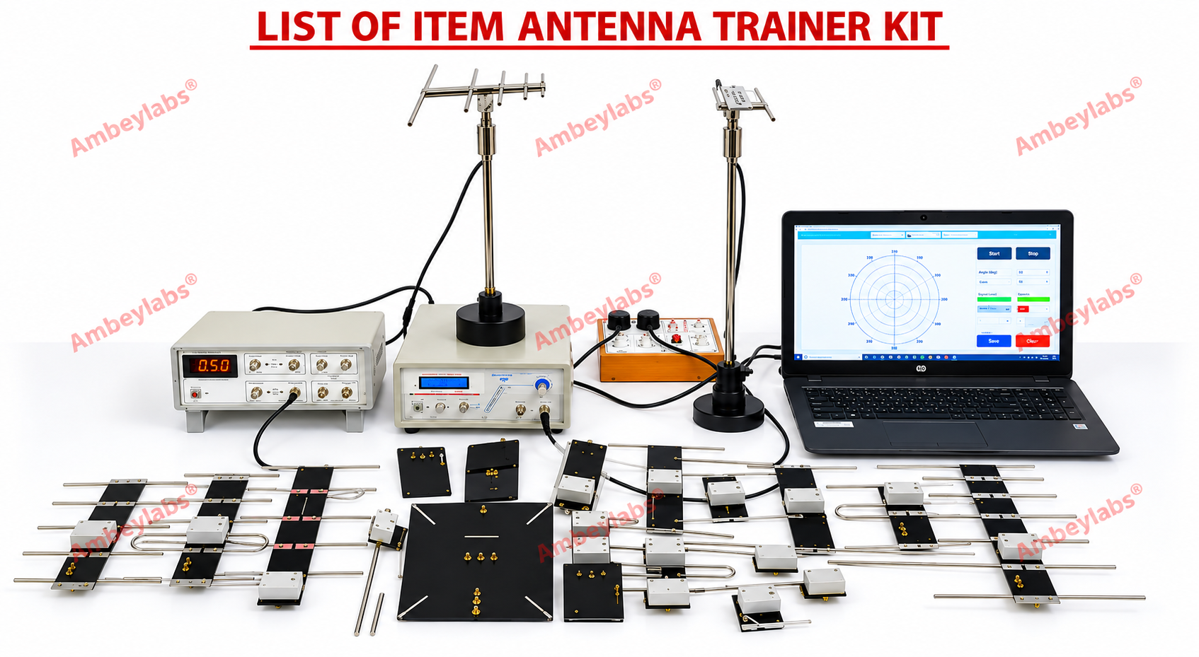
AL-E500C MOTORISED ANTENNA TRAINER
(MOTORISED AND PLOTTING SOFTWARE)
AL-E500C MOTORISED ANTENNA TRAINER
Detailed Technical Specifications – Motorised &
Radiation Pattern Plotting System
1. General
Description
The AL-E500C Motorised Antenna Trainer is a
desktop, self-contained antenna training and measurement system designed for
practical study of antenna characteristics, radiation patterns, polarisation,
antenna matching, SWR, modulation/demodulation and related RF experiments.
The system comprises an RF generator, modulation
generator, transmitting antenna assembly, receiving antenna/detector system,
directional coupler, matching stub, motorised antenna rotation mechanism,
digital indication and PC-based radiation-pattern plotting software.
The motorised section uses a
microcontroller-controlled stepper motor to rotate the antenna through 0–360°
with 1° resolution, enabling automated acquisition and plotting of
radiation patterns through an RS232 serial interface. These core
specifications are also reflected in currently published motorised
antenna-trainer documentation.
2. Scope of
Learning / Experiments
The system shall be suitable for conducting the
following experiments:
1.
Study of
radiation patterns of different antennas.
2.
Polar plot
generation.
3.
Polarisation
study.
4.
Wave
modulation and demodulation.
5.
Antenna
gain study.
6.
Antenna
beam-width measurement.
7.
Study of
element current.
8.
Front-to-back
ratio measurement.
9.
Antenna
matching.
10.
Matching-stub
study.
11.
SWR
measurement.
12.
Forward
and reverse RF power measurement.
13.
Antenna
radiation with distance.
14.
Automated
radiation-pattern measurement.
15.
Computer-based
polar/radiation-pattern plotting.
16.
Comparative
study of different antenna configurations.
17.
Study of
directional and non-directional antenna characteristics.
18.
Study of
antenna arrays.
19.
Study of
reflector and Yagi-UDA antennas.
20.
Fabrication
and testing of special antennas using the supplied antenna fabrication kit.
The published product documentation likewise
identifies polar plots, polarisation, modulation/demodulation, gain, beam
width, element current, front-to-back ratio, matching, SWR and
radiation-versus-distance as learning areas.
3. Main
Features
·
Self-contained
tabletop training platform.
·
Student-friendly
operating arrangement.
·
Modular
antenna construction.
·
Provision
for practical measurement of antenna characteristics.
·
Built-in
RF generator.
·
Built-in
modulation/tone generator.
·
Adjustable
RF output.
·
Adjustable
modulation output.
·
Directional
coupler with forward/reverse selection.
·
Slider-type
matching stub.
·
Digital
measurement indication.
·
Motorised
antenna rotation.
·
Microcontroller-based
motor control.
·
High-precision
stepper-motor mechanism.
·
Automatic
home/reference-position setting.
·
360°
antenna rotation.
·
1° angular
resolution.
·
Real-time
radiation-pattern acquisition.
·
PC
interface through RS232 serial communication.
·
Windows-compatible
radiation-pattern plotting software.
·
Polar
graph generation.
·
Provision
for manual as well as automated measurements.
·
Receiving
antenna with reflector and digital meter.
·
BNC-based
RF interconnection.
·
Compact
construction.
·
Lightweight
arrangement.
·
Carrying
case for accessories.
4. RF
Generator
|
Parameter |
Specification |
|
Generator type |
RF signal generator |
|
Waveform |
Sine wave |
|
RF frequency |
750 MHz approximately |
|
Output |
Adjustable |
|
Application |
RF excitation of transmitting antenna |
|
Output control |
Variable/adjustable |
|
Application frequency |
Suitable for supplied antenna-training experiments |
The approximately 750 MHz adjustable RF generator
is consistent with published specifications for this class of motorised antenna
trainer.
5.
Modulation / Tone Generator
|
Parameter |
Specification |
|
Generator |
Modulation/Tone generator |
|
Frequency |
1 kHz approximately |
|
Output |
Adjustable |
|
Waveform |
Sine |
|
Application |
Modulation/demodulation experiments |
|
Control |
Adjustable output |
6. Motorised
Antenna Unit
|
Parameter |
Specification |
|
Motor type |
Microcontroller-controlled stepper motor |
|
Rotation |
0–360° |
|
Angular resolution |
1° |
|
Direction |
Forward / Reverse |
|
Controls |
Start / Stop |
|
Speed control |
Slow / Fast |
|
Reference |
Automatic home-position setting |
|
Control system |
Microcontroller based |
|
Application |
Automated antenna radiation-pattern measurement |
|
Data acquisition |
PC interface |
|
Interface |
RS232 serial port |
|
Software |
Windows-compatible radiation-pattern plotting
software |
|
Plotting |
Instant/real-time radiation-pattern plotting |
|
Output |
Display, save/print radiation pattern |
Published documentation describes the motorised
system as microcontroller-based, with automatic home positioning, 1° rotation
resolution and RS232 PC communication.
7. Radiation
Pattern Plotting Software
The supplied software shall provide facilities for:
·
PC
communication with the motorised antenna unit.
·
Receiving
angular-position information.
·
Capturing
detector readings.
·
Displaying
radiation-pattern data.
·
Generating
polar/radiation plots.
·
Real-time
pattern display.
·
Recording
the antenna response over the selected angular range.
·
Saving experimental
results.
·
Printing
radiation-pattern graphs.
·
Automated
360° antenna scanning.
·
1°
measurement interval capability.
The published description specifies PC-based
capturing, displaying and printing of antenna radiation patterns through an
RS232 interface.
8.
Directional Coupler
|
Parameter |
Specification |
|
Type |
Directional coupler |
|
Measurement |
Forward / Reverse |
|
Selection |
Selectable |
|
Application |
Measurement of forward and reflected/reverse RF
levels |
|
Use |
SWR and antenna matching experiments |
9. Matching
Stub
|
Parameter |
Specification |
|
Type |
Slider type matching stub |
|
Function |
Antenna impedance/matching study |
|
Application |
Matching and SWR experiments |
|
Adjustment |
Mechanical slider |
10.
Receiving Antenna
|
Parameter |
Specification |
|
Type |
Folded dipole |
|
Reflector |
Provided |
|
Detector arrangement |
Digital meter |
|
Function |
Receive RF radiation from transmitting antenna |
|
Application |
Radiation-pattern measurement |
The folded-dipole receiving antenna with reflector
and digital indication is specified in published documentation for this system
family.
11. RF
Detector
|
Parameter |
Specification |
|
Detector type |
Active RF detector |
|
Connector |
5-pin DIN |
|
Function |
RF signal detection |
|
Output |
Measurement indication to detector/display system |
|
Application |
Radiation-pattern measurement |
12. Detector
Display
·
Digital
meter provided on the main panel.
·
Used for
observing receiving/detected RF level.
·
Suitable
for manual radiation-pattern measurements.
·
Used as
the measurement source for automated plotting.
·
Detector
response can be recorded against antenna angular position.
13. RF
Interconnection
|
Parameter |
Specification |
|
Primary RF interconnection |
BNC |
|
Cable system |
BNC-BNC |
|
Accessories |
BNC Tee and BNC adapters |
|
Detector connection |
5-pin DIN |
|
PC communication |
RS232 |
Note: Published
versions of closely related antenna trainers use different panel
interconnection conventions, so the exact connector type on the supplied
AL-E500C panel should be treated as the controlling specification.
14.
Electrical Specifications
|
Parameter |
Specification |
|
Supply voltage |
110/220 V AC ±10% |
|
Frequency |
50/60 Hz |
|
RF generator power consumption |
3 VA |
|
Motorised unit power consumption |
2 VA |
|
Operating temperature |
0–40°C |
|
Relative humidity |
Up to 80% RH |
15.
Mechanical Specifications
RF Generator Unit
|
Parameter |
Specification |
|
Width |
285 mm |
|
Depth |
385 mm |
|
Height |
75 mm |
|
Weight |
Approximately 3 kg |
Motorised Antenna Unit
|
Parameter |
Specification |
|
Width |
285 mm |
|
Depth |
390 mm |
|
Height |
88 mm |
|
Weight |
Approximately 3 kg |
16. Antenna
Construction
The antennas shall be constructed using
high-conductivity rods with a chrome finish for durability.
The antennas shall be mounted on glass-epoxy PCB
material to permit convenient mounting and dismounting.
The modular arrangement shall permit students to
interchange antenna configurations for comparative experiments.
Published documentation similarly describes
high-conducting antenna rods with chrome finish and glass-epoxy PCB mounting.
17.
Transmitting Antennas – 22 Types
The system shall be supplied with the following
antenna assemblies:
|
S. No. |
Antenna Type |
Qty. |
|
1 |
Simple Dipole λ/2 |
1 No. |
|
2 |
Simple Dipole λ/4 |
1 No. |
|
3 |
Simple Dipole 3λ/2 |
1 No. |
|
4 |
Folded Dipole λ/2 |
1 No. |
|
5 |
Yagi-UDA Folded Dipole – 3 Element |
1 No. |
|
6 |
Yagi-UDA Folded Dipole – 5 Element |
1 No. |
|
7 |
Yagi-UDA Simple Dipole – 5 Element |
1 No. |
|
8 |
Yagi-UDA Simple Dipole – 7 Element |
1 No. |
|
9 |
Hertz Antenna |
1 No. |
|
10 |
Zeppelin Antenna |
1 No. |
|
11 |
λ/2 Phase Array |
1 No. |
|
12 |
λ/4 Phase Array |
1 No. |
|
13 |
Combined Co-linear Array |
1 No. |
|
14 |
Broad-Side Array |
1 No. |
|
15 |
Log Periodic Antenna |
1 No. |
|
16 |
Cut Paraboloid Antenna |
1 No. |
|
17 |
Loop Antenna |
1 No. |
|
18 |
Rhombus Antenna |
1 No. |
|
19 |
Ground Plane Antenna |
1 No. |
|
20 |
Slot Antenna |
1 No. |
|
21 |
Helix Antenna |
1 No. |
|
22 |
Detector Antenna |
1 No. |
18.
Ground-Plane Antenna Rods
|
S. No. |
Rod Length |
Quantity |
|
1 |
6.9 cm |
1 No. |
|
2 |
8.5 cm |
1 No. |
|
3 |
20.5 cm |
1 No. |
19.
Mechanical / Measurement Accessories
|
Item |
Quantity |
|
Current Probe |
1 No. |
|
Transmitting Mast |
1 No. |
|
Receiving Mast |
1 No. |
|
RF Detector |
1 No. |
|
Aligner 932 |
1 No. |
|
Carrying Case |
1 No. |
20. BNC Accessories
|
Accessory |
Quantity |
|
BNC–Tee |
1 No. |
|
BNC–BNC Adapter (M) |
1 No. |
|
BNC–BNC Adapter (F) |
1 No. |
|
BNC (M)–BNC (F) L-Type Adapter |
1 No. |
|
BNC–BNC Cable, 25 inch |
2 Nos. |
|
BNC–BNC Cable, 18 inch |
1 No. |
|
BNC–BNC Cable |
1 No. |
21. Antenna
Fabrication Kit
The system shall include facilities for
fabrication/testing of special antenna configurations.
|
Item |
Quantity |
|
PCB |
1 No. |
|
14 SWG wire roll, 20 inch |
1 No. |
|
Antenna fabrication kit |
25 Nos. as specified |
22.
Additional Accessories
|
Accessory |
Quantity |
|
Polar Graphs – dBuA |
25 Nos. |
|
Polar Graphs – Normalised Reading |
25 Nos. |
|
Mains Cord |
2 Nos. |
|
+5 V DC Adapter, 500 mA |
1 No. |
|
5-Pin DIN Cable |
1 No. |
|
Patch Cords |
1 No. |
|
RS232 Cable |
1 No. |
|
Radiation Pattern Plotting Software |
1 No. |
|
Carrying Case |
1 No. |
23. PC
Interface & Data Acquisition
The system shall provide:
·
RS232
serial communication with PC.
·
Microcontroller-based
antenna-position control.
·
Automatic
antenna rotation.
·
Angular
position resolution of 1°.
·
Detector-response
acquisition.
·
Computer
display of radiation pattern.
·
Real-time
plotting capability.
·
·
Automatic
home/reference positioning.
24. Required
Performance
The system shall allow students to:
1.
Select an
antenna.
2.
Mount the
antenna on the transmitting mast.
3.
Establish
the receiving antenna position.
4.
Apply RF
excitation.
5.
Rotate the
antenna manually or automatically.
6.
Measure
the detector response as a function of angle.
7.
Record
readings at defined angular intervals.
8.
Generate a
polar radiation pattern.
9.
Determine
main-lobe direction.
10.
Determine
null directions.
11.
Estimate
beam width.
12.
Determine
front-to-back relationship for directional antennas.
13.
Compare
radiation patterns of different antenna types.
14.
Study the
effect of antenna polarisation.
15.
Perform
matching and SWR experiments.
25. Suggested Tender Specification
Supply, installation and demonstration of a desktop
AL-E500C Motorised Antenna Trainer with radiation-pattern plotting software,
suitable for undergraduate/postgraduate RF and communication engineering laboratories.
The system shall comprise an approximately 750 MHz adjustable RF generator,
approximately 1 kHz adjustable modulation generator, forward/reverse selectable
directional coupler, slider-type matching stub, microcontroller-based motorised
antenna rotation system covering 0–360° with 1° resolution, automatic home
positioning, active RF detector with 5-pin DIN connector, folded-dipole
receiving antenna with reflector and digital meter, RS232 PC interface,
Windows-compatible radiation-pattern plotting software, BNC interconnection
accessories, transmitting/receiving masts, current probe, antenna fabrication
kit, polar graph sheets, carrying case and the specified set of 22 antenna
configurations. The system shall support practical experiments covering polar
plots, polarisation, modulation/demodulation, antenna gain, beam width, element
current, front-to-back ratio, antenna matching, SWR, radiation with distance
and automated computer-based radiation-pattern plotting.