

AL-E425E SINGLE PHASE RLC CIRCUIT TRAINER (POWER, POWER FACTOR AND RESONANCE)
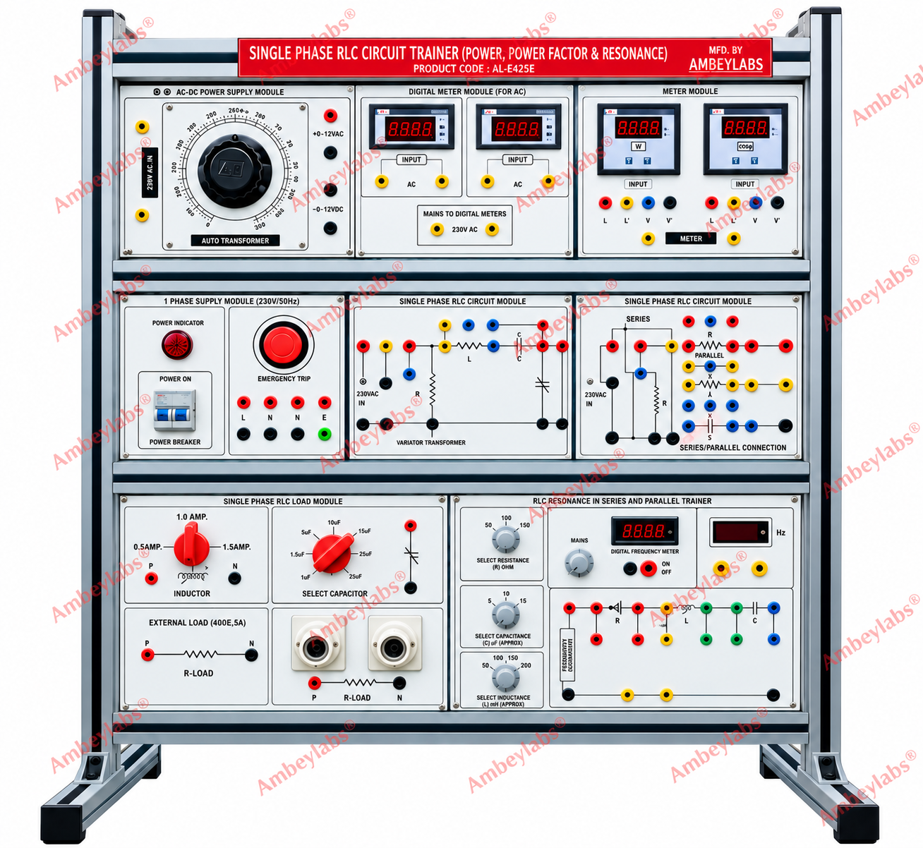
Project Information
- Category: ELECTRICAL ENGINEERING
- Sub Category: ELECTRICAL ENGINEERING
- Model Number: AL-E425E
Description
AL-E425E SINGLE PHASE RLC CIRCUIT
TRAINER (POWER, POWER FACTOR AND RESONANCE)
Detailed Technical Specifications
AL-E425E Single Phase RLC
Circuit Trainer (Power, Power Factor and Resonance)
Product category: Electrical
Engineering Laboratory
Product Code: AL-E425E
1. Product Description
The AL-E425E Single Phase
RLC Circuit Trainer is an educational laboratory system designed for studying
AC circuit power, power factor, series and parallel RLC circuits, resonance and
quality factor. The trainer incorporates a variable AC power supply, sine wave
generator, digital electrical measuring instruments, selectable resistors,
capacitors and inductors, and dedicated resonance circuit panels. The equipment
is housed in a modular aluminium-extruded rack with an insulated front panel,
printed circuit diagrams and colour-coded connection sockets.
2. Detailed Technical Specifications
|
S. No. |
Parameter |
Specification |
|
1 |
Product name |
Single Phase RLC Circuit
Trainer |
|
2 |
Model / Product code |
AL-E425E |
|
3 |
Application |
Power, power factor and
resonance studies |
|
4 |
AC power supply |
0–230 V AC, 4 A |
|
5 |
Mains supply |
230 V, 50 Hz, ±10% |
|
6 |
Signal generator |
Sine wave generator, 0–100
kHz |
|
7 |
Digital meters |
Voltmeter, ammeter,
wattmeter and power factor meter |
|
8 |
Resonance circuit ammeter |
20 mA AC |
|
9 |
Frequency counter |
Up to 40 MHz, as specified
in the supplied document |
|
10 |
Variable resistor |
400 Ω, 2 A |
|
11 |
Capacitor selection |
Six capacitors selected
through rotary switches |
|
12 |
Inductor selection |
Three inductors selected
through rotary switches |
|
13 |
Additional resistor
selection |
Three resistors selected
through a rotary switch |
|
14 |
Additional capacitor
selection |
Three capacitors selected
through a rotary switch |
|
15 |
Additional inductor
selection |
Three inductors selected
through a rotary switch |
|
16 |
Front panel |
Insulated sheet with
printed circuit diagrams & symbols |
|
17 |
Construction |
Modular rack-type
aluminium-extruded metal cabinet |
|
18 |
Connection system |
4 mm heavy-duty patch
cords |
|
19 |
Test points |
4 mm safety sockets for
high-voltage test points |
|
20 |
Protection |
Emergency stop and
MCB-based short-circuit protection |
|
21 |
Approximate dimensions |
30 × 24 inches, as stated
in the source |
|
22 |
Instruction manual |
Included |
|
23 |
Optional accessories |
Oscilloscope |
|
24 |
Manufacturer |
Ambey International |
3. Scope of Learning
The trainer is designed to
support the following studies:
1.
Study of power and power factor in AC RLC circuits.
2.
Analysis of series-connected RLC circuits.
3.
Analysis of parallel-connected RLC circuits.
4.
Study of RLC resonance in series circuits.
5.
Study of RLC resonance in parallel circuits.
6.
Measurement of AC voltage and current.
7.
Measurement of electrical power using a wattmeter.
8.
Measurement and analysis of power factor.
9.
Investigation of the effect of resistance, capacitance and inductance on
circuit behaviour.
10.
Study of quality factor in resonant circuits.
4. Functional Modules
4.1 AC Power
Supply Module
·
Adjustable AC output from 0–230 V AC.
·
Current rating of 4 A, as specified.
·
Designed for supplying the experimental circuits.
4.2 Sine Wave
Generator
·
Frequency range of 0–100 kHz.
·
Provides a sine wave signal for frequency-dependent circuit
investigations.
4.3 Digital
Meter Module
·
Digital voltmeter.
·
Digital ammeter.
·
Digital wattmeter.
·
Digital power factor meter.
4.4 RLC Circuit
Module
·
Panel-mounted circuit arrangements for series and parallel connections.
·
Selectable resistor, capacitor and inductor components.
·
Rotary switches for component selection.
4.5 Resonance
Measurement Module
·
Dedicated resonance circuit measurement section.
·
20 mA AC ammeter.
·
Frequency counter specified up to 10 MHz.
·
Controls for selecting circuit parameters.
5. Construction and Safety Features
- Modular
aluminium-extruded metal rack.
- Insulated Bakelite
front panel.
- Printed circuit
diagrams and component symbols.
- 4 mm heavy-duty patch
cords for circuit connections.
- 4 mm safety sockets at
designated high-voltage test points.
- Emergency stop
facility.
- MCB-based short-circuit
protection.
- Instruction manual
supplied with the equipment.
OPTIONAL
ACCESSORIES:
· No