

AL-E297 THREE PHASE SLIP RING INDUCTION MOTOR (CUT SECTION MOTOR)
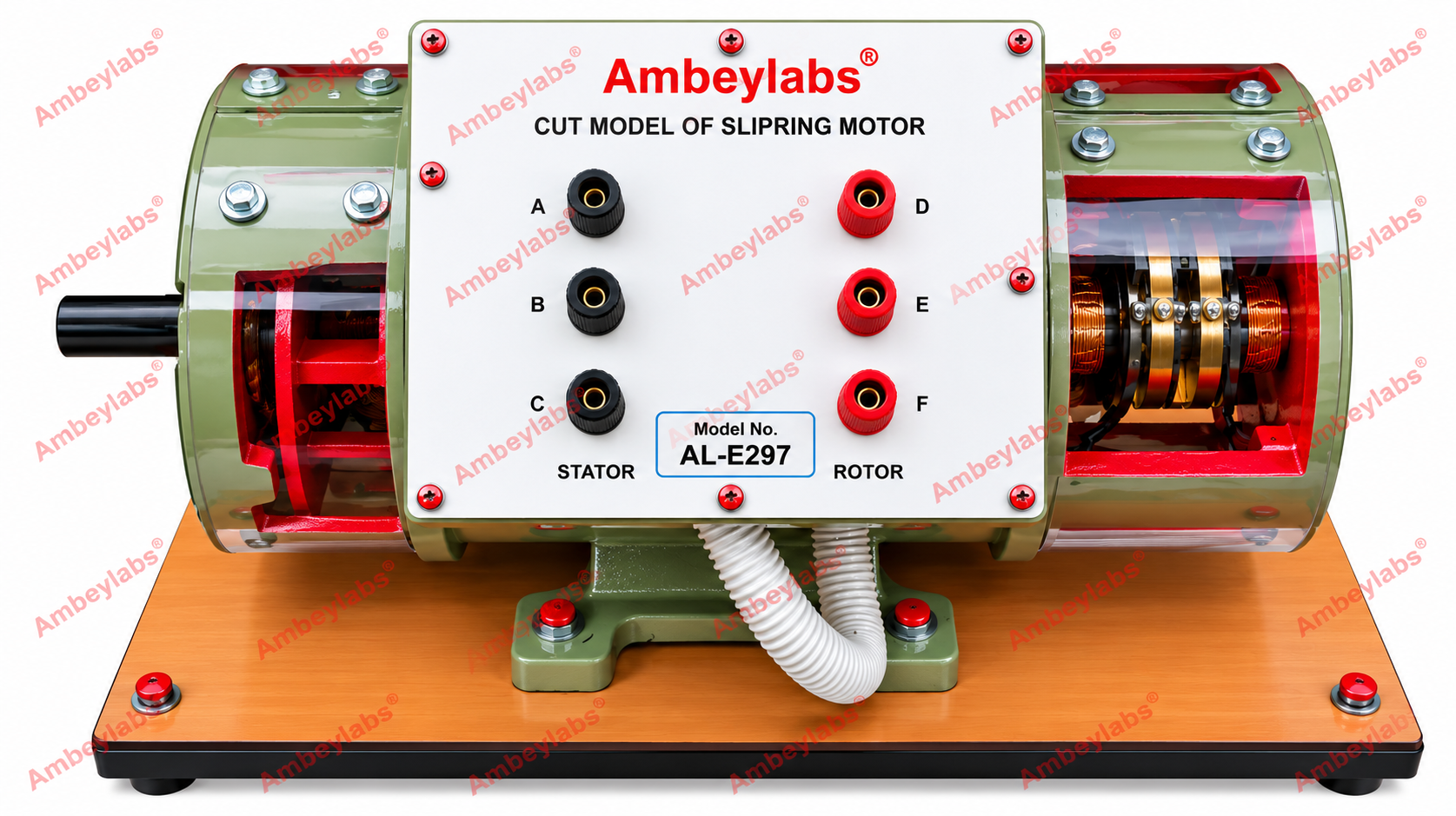
Project Information
- Category: ELECTRICAL ENGINEERING
- Sub Category: CUT SECTION MOTORS
- Model Number: AL-E297
Description
AL-E297
THREE PHASE SLIP RING INDUCTION MOTOR
(CUT
SECTION MOTOR)
MODEL NO: AL-E297
Detailed Technical Specifications
-------------------------------------------------------------------------------------------------------------------------------------------Product Code: AL-E297 Product Name: Three-Phase
Slip Ring Induction Motor Category: Electrical Machines Training Equipment
1. Technical Specifications
|
S. No. |
Parameter |
Technical Specification |
|
1 |
Type of Motor |
Three-Phase AC Slip Ring Induction
Motor |
|
2 |
Rated Power |
1 HP (0.75 kW) |
|
3 |
Operating Voltage |
415 V AC, three-phase |
|
4 |
Rated Speed |
1440 RPM |
|
5 |
Motor Type |
AC Induction Motor |
|
6 |
Rotor Construction |
Wound Rotor with Slip Rings |
|
7 |
Terminal Connections |
6 BTI 15 terminals, as specified |
|
8 |
Shaft Arrangement |
Single shaft |
|
9 |
Frame Size |
132 |
|
10 |
Mounting Arrangement |
B3 – Foot-mounted |
|
11 |
Stator Construction |
Laminated steel core with three-phase
windings |
|
12 |
Rotor Construction |
Wound rotor with three-phase rotor
windings connected to slip rings |
|
13 |
Slip Ring Assembly |
Provided for external rotor circuit
connections |
|
14 |
Yoke |
Solid yoke extension |
|
15 |
Enclosure Designation |
SPDP, as specified |
|
16 |
Protection Rating |
IP23, subject to manufacturer
confirmation |
|
17 |
Cooling Designation |
IC01, as specified |
|
18 |
Mounting Base |
Rigid metal base |
|
19 |
Shaft |
Single output shaft |
|
20 |
Application |
Electrical machines laboratory and
engineering training |
2. Constructional Features
- Stator assembly: Laminated steel core
accommodating three-phase stator windings to generate the rotating magnetic
field.
- Wound rotor: Contains a three-phase
rotor winding designed for connection to an external resistance circuit
through slip rings.
- Slip ring assembly: Provides
electrical access to the rotor windings for studying starting
characteristics and speed control.
- Brush arrangement: Suitable brush
contacts provide electrical connections between the stationary external
circuit and rotating slip rings, where included in the supplied design.
- Single shaft: Provides the mechanical
output and supports the rotating assembly.
- Solid yoke extension: Incorporates the
specified structural extension.
- Terminal arrangement: Six specified
terminals for instructional connection and demonstration, subject to the
actual terminal configuration.
- Mounting base: Rigid metal base for
secure installation in laboratory environments.
3. Experiments and Learning Objectives
The AL-E297 is suitable for the
following laboratory experiments:
- Study of the construction and working
principle of a three-phase slip ring induction motor.
- Identification of stator, wound rotor,
slip rings, brushes, and shaft.
- Study of rotor resistance starting
methods.
- Investigation of the effect of
external rotor resistance on starting torque.
- Study of speed control by varying
external rotor resistance.
- Observation of the relationship
between load, speed, and slip.
- Study of three-phase stator and rotor
winding connections.
- Comparison of slip ring and squirrel
cage induction motors.
- Understanding rotor copper losses and
efficiency characteristics.
4. Working Principle
When a three-phase AC supply is applied
to the stator windings, a rotating magnetic field is produced. This field
induces an electromotive force and current in the wound rotor. The interaction
between the stator field and rotor current produces electromagnetic torque,
causing the shaft to rotate.
The slip rings allow external
resistance to be inserted into the rotor circuit. During starting, this
resistance can improve starting torque and limit starting current. Reducing the
external resistance as the motor accelerates enables normal operation. External
rotor resistance can also be used to demonstrate speed control, although it
introduces additional power losses.
5. General Requirements
- Suitable for electrical machines
laboratories, engineering colleges, polytechnics, and technical training
institutions.
- Robust construction for repeated
educational use.
- Accessible components for observation
and demonstration.
- Slip rings and rotor connections
suitable for instructional experiments.
- Clearly identified terminals for
connection and testing.
- Secure installation on a rigid metal
base.
- Operation with suitable electrical
protection and under qualified supervision.
Technical verification note: The
designations SPDP, 1P23, and 1C01 have been retained or interpreted from the
supplied specifications. Confirm the exact enclosure, IP protection rating, and
cooling classification with the manufacturer before using this document for a
formal tender. The stated six-terminal arrangement should also be checked
against the motor's actual winding and terminal diagram.