

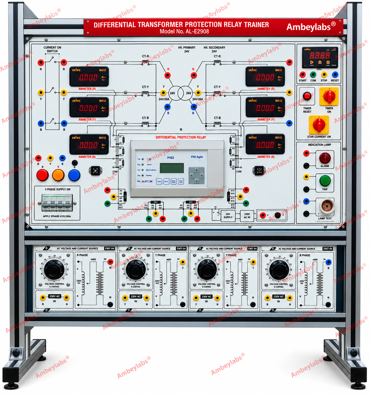
AL-E290C 3PHASE PERCENTAGE BIASED DIFFERENTIAL PROTECTION RELAY TRAINER // WITHOUT PC INTERFACE
Project Information
- Category: ELECTRICAL ENGINEERING
- Sub Category: POWER SYSTEM AND PROTECTION LAB
- Model Number: AL-E290C
Description
AL-E290C 3PHASE
PERCENTAGE BIASED DIFFERENTIAL
PROTECTION RELAY TRAINER // WITHOUT PC INTERFACE
Overview
The AL-E290A is a comprehensive modular training system designed for hands-on study of percentage biased differential protection relays (Merz-Price method). It enables students and professionals to understand, test, and analyze transformer differential protection under both in-zone and out-of-zone fault conditions in a safe, controlled laboratory environment.
Scope of Learning
- Plot characteristics of percentage biased differential relay (Merz-Price method)
- Perform pick-up test for differential relay
- Study transformer protection for in-zone trip faults
- Study transformer protection for out-of-zone / through faults (non-trip conditions)
Technical Specifications of measuring instruments and power
supply on control panel
- AC supply: 0–415 V, 5A autotransformer; mains 415 V, 50 Hz ±10 %. 24V-220V dc for Numerical relay with protection from overvoltage and undervoltage and overload conditions
- 4-pole MCB (415 V / 16 A), R-Y-B indication, contactor, emergency stop, R-Y-B-N distribution.
- Digital meters voltmeters (AC 500 V), ammeters (AC 20 A), multifunction meter (V, I, Hz, PF, kVA, kW, kWh with optional Modbus RTU), connected with CTs internally 30/5 3no.
- Digital timer to measure the elapsed time between Normal to trip.
- Tripping indication,lamps for normal/trip status.
Salient Features
ü Input 3 phase input
starter panel , 4 pole MCB of 415V/2A or single phase supply with MCB control
, A control Contactor with
230/50Hz/11VACoil, start and stop buttons to turn on the control panel for safe
operation, electronics O/L Relay with
range 1-30A (settable) . R-Y-B Input Indicators.
ü Green SBS5
socket is provided for extend earth.
ü Emergency stop
switch to stop the panel in extreme hazordous conditions
ü A tower
light to show the indications of the
panel status , Red for fault , yellow for stop, Green for normal working
conditions.
ü Front panel built with high class insulated Printed Circuit Board sheet
with well printed circuits and symbols.
ü The trainer frame housed in Modular Rack Type Aluminum Extruded 40x40
channel.
ü MCB for Short Circuit protection
ü Instruction manual with complete detailed programs and installation
procedures included.
ü Connections are brought out through 4mm Colored Sockets.
ü Required no’s of Patch Cords 4mm will be provided along with trainer
ü The trainer modules are housed in MS cabinet duly powder coated
ü Ensuring secure earthing provided into the panel for human being safety
Modules specification in control panel Module EMT-1 – Power
Control Unit
- 4-pole MCB, 415 V / 16 A
·
Input
3 phase input starter panel , 4 pole MCB of 415V/2A or single phase supply with
MCB control , A control Contactor with
230/50Hz/11VACoil, start and stop buttons to turn on the control panel for safe
operation, electronics O/L Relay with
range 1-30A (settable) . R-Y-B Input Indicators.
- 3-phase power indication (R-Y-B)
- Emergency stop push-button to terminate the control panel in case of hazardous conditions
- R-Y-B-N output distribution terminals
- Ensuring the complete earthing of the control panel for human safety
Module EMT-4 – Multifunction Meter
- Bidirectional multifunction meter, 3-phase 3/4-wire, 415 V AC
- CT input: 5 A connected inside in each phase
- LCD/LED display
- Auxiliary supply: 230 V, 45–65 Hz, 5 W
- Measured parameters: Voltage, Current, Frequency, Power Factor, kVA, kW, kWh
- Optional Modbus RTU (RS-485) for RTU/SCADA interface
Module EMT-2 (×3)
- Digital voltmeter: AC 500 V
- a digital timer with Start/Stop and Reset functionswith start and stop input sockets
- Operable on 230 V AC)
Tripping Indication And current transformer module
- Two lamp holders (230 V), One module of 2 CTS of required rating mounted on board
- Indication for Normal and Trip conditions
Voltage transformer module
PTs 3 nos with Voltage transformer is provided
The voltage transformer of required rating as per the design requirement
Differential Protection Relay Module
Key Features
- Biased current differential protection
- Fast differential Hi-set
- Dual-slope characteristics
- Inbuilt CT ratio correction factor (avoids
external interposing CTs)
- Adjustable 2nd harmonic restraint (for
inrush)
- Adjustable 5th harmonic blocking (for
over-excitation)
- Inbuilt vector group compensation
- Two groups of settings
- History of 5 latest faults
- Stability on external phase-to-phase and
phase-to-ground faults
Technical
Specifications (from manufacturer data)Ratings
- Primary current rating: 0.577 A / 1 A /
2.89 A / 5 A
- Secondary current rating: 0.577 A / 1 A /
2.89 A / 5 A
- Auxiliary supply:
- 20–60 V DC
- 75–150 V DC (or AC/DC in some
listings)
- 175–300 V DC / 185–250 V AC
Settings
- Pickup (
- Slope1 (DF1): 10 to 100% (steps of 5%)
- Slope2 (DF2): 50 to 200% (steps of 5%)
- Breakpoint (
- Differential Hi-set: 2 to 20 pu (steps of
1 pu)
- CT Ratio W1: 0.5 to 2.00 pu (steps of 0.01
pu)
- CT Ratio W2: typically in related
percentage steps (manufacturer lists 10–50% in some extracts)
- Inrush (2nd harmonic): 10 to 100% (steps
of 5%)
- Over-excitation (5th harmonic): adjustable
- Vector groups supported: Yy0, Dd0, Yd1,
Dy1, Dd2, Dd4, Yd5, Dy5, Yy6, Dd6, Yd7, Dy7, Dd8, Dd10, Yd11, Dy11 (and
similar)
Overload Ratings
(Current Inputs)
- 2 × rated continuous
- 20 × rated for 3 s
- 40 × rated for 1 s
Burden
- Current input: 0.1 VA per phase (rated 5
A); 0.05 VA per phase (rated 1 A)
- Auxiliary supply: < 6 W (non-operated);
< 11 W (operated)
3-Phase Voltage and Current Source Module
- Dedicated circuit for Differential Protection Relay experiments
- 4A autotransformer, 3 no’s to vary the voltage from 0-230V, 50HZ line to neutral & 415V,50Hz line to line with 0-48V, 10A output to bias of transformer primary winding, output voltage provided through 4 mm safety sockets
Packing List (Standard Supply)
|
Item |
Description |
|
AL-E290A |
3-Phase Percentage Biased Differential Protection Relay Trainer |
|
AL-E295 |
3-Phase Transformer Unit (Star/Delta), 415/230 V AC, 3 KVA |
|
— |
Patch Cords (Heavy Duty) |
|
AL-E277 |
3-Phase Resistive Load (Lamp Load) |
|
— |
Filament Lamps (2 units) |