

AL-E1104 AIR TO AIR HEAT PUMP TRAINER
Project Information
- Category: MECHANICAL ENGINEERING
- Sub Category: RAC LAB
- Model Number: AL-E1104
Description
AL-E1104
AIR TO AIR HEAT PUMP APPARATUS
Detailed
Technical Specifications
Air–Air Heat Pump
Trainer
Model
AL-E1104
---------------------------------------------------------------------------------------------------------------------------------------1. General Description
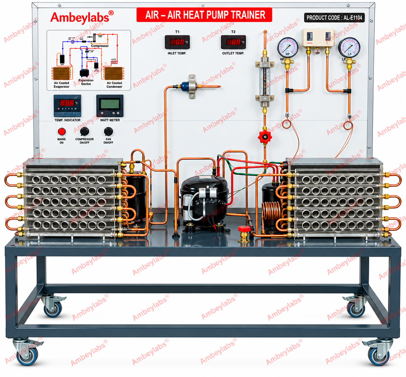
The Air–Air Heat Pump Trainer is designed for the study and
demonstration of the operating principles of an air-to-air heat pump and its
refrigeration cycle. The trainer consists of a compressor, evaporator,
condenser, expansion device, refrigerant piping, pressure gauges, a flow meter,
temperature indicators, electrical controls, and a circuit diagram mounted on a
panel.
The equipment is suitable for refrigeration and air-conditioning
laboratories, polytechnic institutes, engineering colleges, and technical
training centres.
2. Detailed Technical
Specifications
|
S. No. |
Parameter |
Specification |
|
1 |
Equipment name |
Air–Air Heat Pump Trainer |
|
2 |
Model number |
AL-E1104 |
|
3 |
Equipment type |
Refrigeration and heat pump training system |
|
4 |
Mounting arrangement |
Panel-mounted trainer on a rigid metal stand |
|
5 |
Frame |
Metal structure with castor wheels for mobility |
|
6 |
Front panel |
Instrumentation and control panel with printed circuit diagram |
|
7 |
Compressor |
Refrigeration compressor |
|
8 |
Evaporator |
Air-cooled heat exchanger |
|
9 |
Condenser |
Air-cooled heat exchanger |
|
10 |
Expansion device |
Expansion device incorporated into the refrigeration circuit |
|
11 |
Refrigerant circuit |
Copper tubing with connecting bends and fittings |
|
12 |
Pressure measurement |
High-pressure and low-pressure gauges |
|
13 |
Temperature measurement |
Digital temperature indicators and associated sensors |
|
14 |
Refrigerant flow measurement |
Flow meter installed in the refrigerant circuit |
|
15 |
Electrical measurement |
Watt meter for monitoring electrical power consumption |
|
16 |
Control system |
Front-panel switches and indicators |
|
17 |
Compressor control |
Dedicated compressor ON/OFF control |
|
18 |
Fan control |
Dedicated fan ON/OFF control |
|
19 |
Main supply indication |
Mains ON indicator |
|
20 |
Circuit diagram |
Refrigeration-cycle schematic displayed on the front panel |
|
21 |
Piping arrangement |
Exposed piping for visual observation of the refrigeration
circuit |
|
22 |
Mobility |
Castor wheels fitted to the supporting frame |
|
23 |
Application |
Study of heat pump operation and refrigeration-cycle parameters |
Note: These specifications are based on the supplied image. Exact
electrical ratings, refrigerant type, cooling/heating capacity, pressure ranges
and instrument accuracy are not confirmed by the image.
3. Main Components and
Functional Details
3.1
Compressor
The trainer incorporates a refrigeration compressor to circulate
refrigerant through the system. It enables students to study the compression
stage and observe the relationship between compressor operation, pressure and
power consumption.
3.2
Evaporator
An air-cooled heat exchanger is provided as the evaporator. It
facilitates heat absorption by the refrigerant and supports the study of
evaporation and low-pressure-side operation.
3.3
Condenser
An air-cooled heat exchanger is installed on the opposite side of
the trainer. It allows observation of heat rejection from the refrigerant and
the condensation process.
3.4
Expansion Device
An expansion device is incorporated into the refrigeration circuit
to reduce refrigerant pressure before it enters the evaporator.
3.5
Refrigerant Piping
Copper tubing, bends and fittings connect the major refrigeration
components. The visible piping arrangement allows students to trace the
refrigerant flow path and identify the individual sections of the cycle.
3.6
Pressure Gauges
High-pressure and low-pressure gauges are provided to observe the
operating pressures of the refrigeration system.
3.7
Temperature Measurement System
Digital temperature indicators and associated sensors are provided
for monitoring temperatures at designated points in the system.
3.8
Refrigerant Flow Meter
A flow meter is incorporated into the circuit for observing
refrigerant flow, subject to the meter's specified operating range.
3.9
Electrical Power Measurement
A watt meter is provided to measure the electrical power consumed
by the equipment during operation.
3.10
Electrical Control Panel
The front panel includes mains indication, compressor and fan
ON/OFF controls, digital instruments, and a printed refrigeration-cycle
diagram.
4. Scope of Learning
The trainer can support the following experiments, depending on
the supplied instrumentation and operating procedure:
1.
Study of the basic principle and operation of an air–air heat
pump.
2.
Identification of the main components of a refrigeration cycle.
3.
Study of the functions of the compressor, evaporator, condenser
and expansion device.
4.
Measurement of high-side and low-side refrigerant pressures.
5.
Observation of temperatures at designated points in the
refrigeration circuit.
6.
Measurement of electrical power consumed by the compressor and
associated equipment.
7.
Observation of refrigerant flow using the installed flow meter.
8.
Study of the relationship between operating pressure, temperature
and heat pump performance.
9.
Understanding of heat absorption at the evaporator and heat
rejection at the condenser.
5. Construction and Safety
Features
·
Rigid metal supporting frame with castor wheels.
·
Panel-mounted instruments and controls.
·
Clearly displayed refrigeration-cycle schematic.
·
Exposed copper piping for visual inspection and instructional
demonstrations.
·
Dedicated compressor and fan controls.
·
Pressure and temperature monitoring instruments.
The equipment should be operated in accordance with the
manufacturer's instructions. Refrigerant charging, servicing and
pressure-circuit maintenance should be performed only by suitably trained
personnel.
6. Standard Equipment
Configuration
The supplied image indicates the following major components:
·
Air–Air Heat Pump Trainer, Model AL-E1104.
·
Refrigeration compressor.
·
Air-cooled evaporator and condenser.
·
Expansion device.
·
Copper refrigerant piping and fittings.
·
High-pressure and low-pressure gauges.
·
Digital temperature indicators.
·
Refrigerant flow meter.
·
Watt meter.
·
Electrical control switches and indicators.
·
Metal supporting frame with castor wheels.