

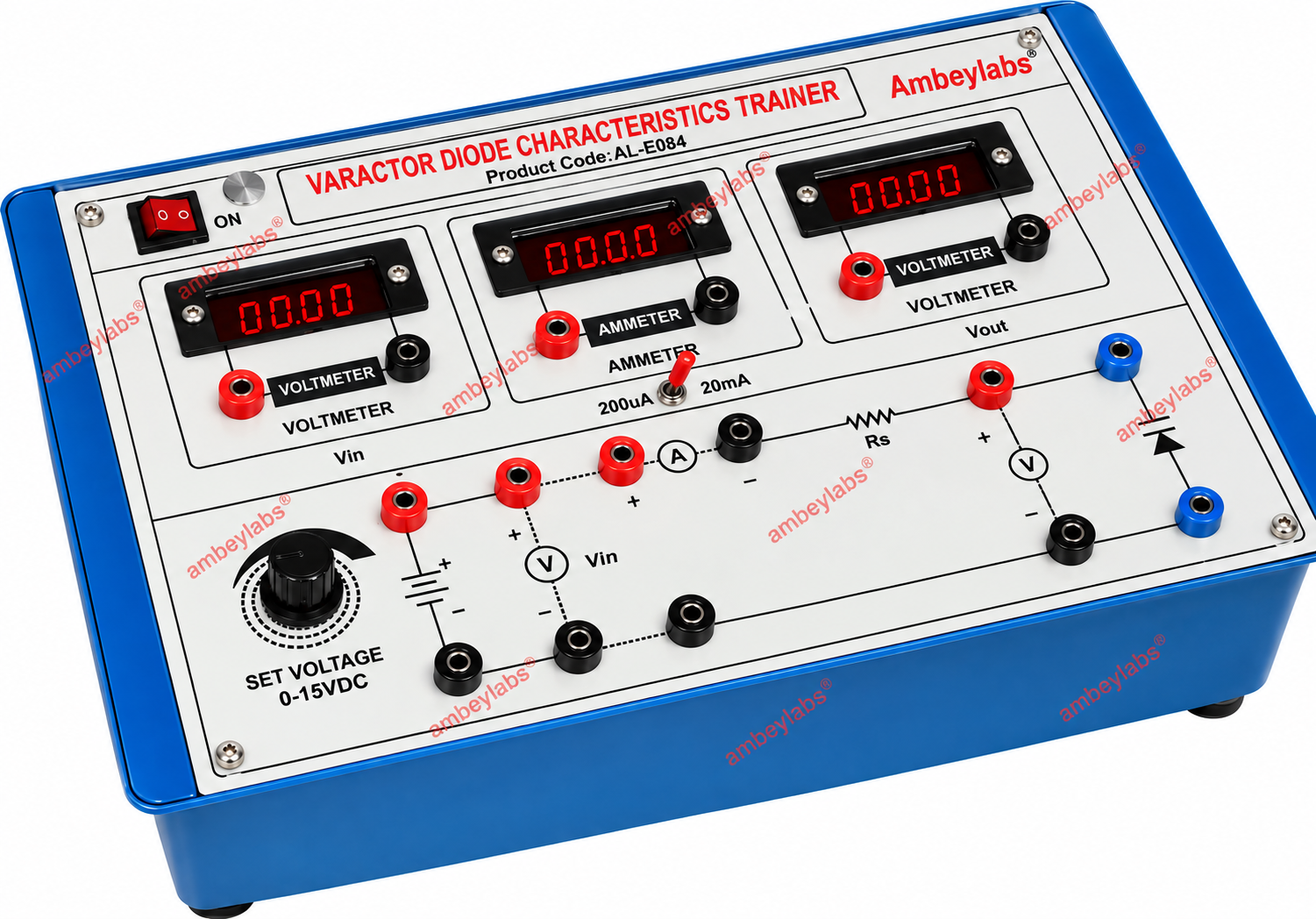
AL-E084 VARACTOR DIODE CHARACTERISTICS TRAINER
Project Information
- Category: ELECTRONICS ENGINEERING
- Sub Category: BASIC ELECTRONICS LAB
- Model Number: AL-E084
Description
AL-E084 VARACTOR
DIODE CHARACTERISTICS TRAINER (DIGITAL)
Product Code: AL-E084
Product Name: Varactor Diode Characteristics Trainer (Digital)
-------------------------------------------------------------------------------------------------------------------------------------------------------
The AL-E084 Varactor Diode
Characteristics Trainer (Digital) is a compact laboratory training system
designed for practical study of the V-I characteristics of a varactor diode.
The trainer integrates regulated DC power, digital voltage/current measurement,
variable voltage control, and a sine-wave oscillator on a single instructional
panel.
2.
Scope of Learning
The trainer is designed for the
following experiment:
- Study of V-I characteristics of a
Varactor Diode.
- Observation of variation in diode
current with applied voltage.
- Measurement of input voltage and
output voltage using onboard digital voltmeters.
- Measurement of diode current using the
onboard digital ammeter.
- Study of voltage-controlled operation
of the varactor diode.
- Practical operation using 4 mm
patch-cord connections.
3.
Digital Measurement Section
|
Parameter |
Specification |
|
Ammeter |
Digital DC Ammeter |
|
Ammeter Range |
200 µA / 20 mA DC |
|
Voltmeter-1 |
Digital DC Voltmeter |
|
Voltmeter-1 Range |
15 V DC |
|
Voltmeter-2 |
Digital DC Voltmeter |
|
Voltmeter-2 Range |
15 V DC |
|
Display |
Digital display |
|
Connection |
4 mm colour-coded terminals |
4.
DC Power Supply
|
Parameter |
Specification |
|
Supply Type |
IC Regulated DC Supply |
|
Output Voltage |
15 V DC |
|
Current Capacity |
150 mA |
|
Input Mains |
230 V AC |
|
Mains Frequency |
50 Hz |
|
Mains Tolerance |
+10% |
|
Protection |
Fuse protection |
5.
Audio Sine-Wave Oscillator
|
Parameter |
Specification |
|
Oscillator Type |
Sine-wave oscillator |
|
Frequency Range |
0–100 kHz |
|
Waveform |
Sine wave |
|
Application |
Signal generation for laboratory
studies |
6.
Varactor Diode Section
The trainer incorporates the following
components directly on the front panel:
- Varactor diode
- Variable voltage control potentiometer
- Input voltage measurement terminals
- Output voltage measurement terminals
- Current measurement terminals
- Circuit connection diagram
- Polarity identification
- Colour-coded input/output terminals
7.
Front Panel Construction
- High-quality insulated PCB front
panel.
- Permanently printed circuit diagram
and operating symbols.
- Clearly identified measurement points.
- Clearly marked positive and negative
terminals.
- Separate sections for voltmeter,
ammeter and varactor diode circuit.
- Panel-mounted controls for convenient
laboratory operation.
- Components and connections arranged
for easy student observation.
8.
Electrical Connections
- All major experimental connections are
brought out to 4 mm colour-coded safety sockets.
- Connections are clearly labelled for:
- Voltage measurement
- Current
measurement
- Varactor diode
circuit
- Input voltage
Optional: Multimeter