

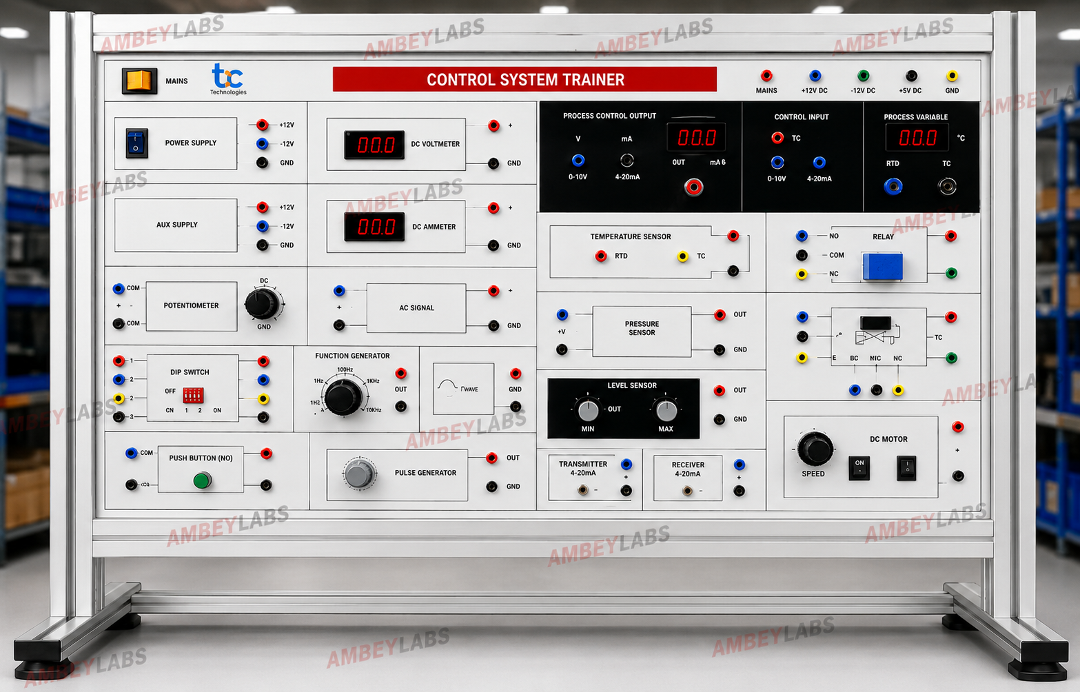
AL-E997 CONTROL SYSTEM LAB TRAINER
Project Information
- Category: ELECTRONICS ENGINEERING
- Sub Category: CONTROL LAB
- Model Number: AL-E997
Description
AL-E997 CONTROL SYSTEM LAB
TRAINER
|
|
||
|
Trainer has various parts like Temperature Sensor, Light Sensor, DC
Motor, Servo Motor, LED lamps, IR Sensor, Relay SPST, Relay DPDT, de-bounce
Switch, LED bar, Buzzer etc., which can be used for study of Control System. Process
can be controlled using P, PI & PID control system There are a wide range
of experiments that can be performed on the platform. Control System Lab is
also compatible with Data Acquisition System. DAQ is very useful for sensing
and controlling analog and digital signals of any process. It makes easy and
interesting to interface real world signals with PC/Laptop through USB bus.
For ease of connection it has screw terminals. |
||
|
Features |
|
||
|
•
Open Loop Control System |
|
||
|
•
Close Loop Control System |
|
||
|
•
On board Temperature Sensor and heater |
|
||
|
•
Feedback concept |
|
||
|
•
P, PI & PID Control System using software |
|
||
|
•
External DC Motor with encoder |
|
||
|
•
On board LED lamp and Light Sensor |
|
||
|
•
On board Buzzer for Alarm |
|
||
|
•
On board Infrared Sensor |
|
||
|
•
On board Relay interface |
|
||
|
•
On board LED bar display |
|
||
|
•
On board Servo Motor control |
|
||
|
•
DC Motor speed control |
|
||
|
•
Light intensity control |
|
||
|
•
V/F, F/V & V/I conversion |
|
||
|
•
Breadboard for circuit design |
|
||
|
Data
Acquisition System |
|
||
|
•
4 Analog Input (ADC) channels |
|
||
|
•
1 Analog Output (DAC) channels |
|
||
|
•
1 PWM Output |
|
||
|
•
22 Digital Input and Output channels |
|
||
|
•
10-bit ADC resolution |
|
||
|
•
Data logging facility |
|
||
|
•
USB interface |
|
||
|
•
Two unity gain given to strengthen the weak signal from any |
|
||
|
Sensor |
|
||
|
•
Removable screw terminals for easy signal connectivity |
|
||
|
•
Exhaustive course material & references |
|
||
|
Scope of Learning |
|
||
|
Study & observe: |
|
||
|
•
Voltage to Frequency converter |
|
||
|
•
Frequency to Voltage converter |
|
||
|
•
Characteristic of Photoconductive cell(LDR) |
|
||
|
•
Motor speed & input characteristics |
|
||
|
•
Position control of Servo Motor |
|
||
|
Study & implement: |
|
||
|
•
Light intensity control using PWM method |
|
||
|
•
Bidirectional Motor speed control |
|
||
|
•
Tachogenerator using F/V converter |
|
||
|
•
Motor control using PWM method |
|
||
|
•
Open-Loop DC Motor control |
|
||
|
•
Closed-Loop DC Motor control |
|
||
|
•
Speed of a DC motor using P, PI & PID controller |
|
||
|
•
Open-Loop Temperature control |
|
||
|
•
Closed-Loop Temperature control |
|
||
|
•
Temperature using P, PI & PID controller |
|
||
|
•
Open-LoopL Light intensity control |
|
||
|
•
Closed-Loop Light intensity control |
|
||
|
•
Study & Control Light Intensity using P, PI & PID
controller |
|
||
|
Technical
Specifications |
|
||
|
Operating
Voltage |
: +5V, - 5V,
+12V, -12V |
|
|
|
Servo
Motor |
: +5VDC |
|
|
|
DC
Motor |
: +12VDC |
|
|
|
Temperature
Sensor |
: 10mV/0C |
|
|
|
Light
Sensor |
: Photo
Conductive Cell (LDR) |
|
|
|
Light
Source |
: 2 LED's |
|
|
|
V/F |
: Input 0-5V |
|
|
|
Output 0-5 KHz
Approximately) |
|
||
|
F/V |
: Input 0-5 KHz |
|
|
|
Output 0-5V
(Approximately) |
|
||
|
V/I |
: 4 to 20mA |
|
|
|
Clock
Generator |
: 0-43.50 KHz |
|
|
|
SPST
Relay |
: +5V |
|
|
|
DPDT
Relay |
: +5V |
|
|
|
De-Bounce
Switch |
: Monostable (5V
output) |
|
|
|
PWM |
: 1 no. |
|
|
|
Buzzer |
: +5V |
|
|
|
Switches |
: IR Switch, DIP
switch |
|
|
|
Test
Points |
: 25 |
|
|
|
DAQ
Analog Inputs |
: 4 Inputs with
10 bit |
|
|
|
resolution |
|
||
|
DAQ
Analog Output |
: 1 Output 10 bit
resolutions |
|
|
|
DAQ
Digital Inputs |
: 11 TTL Inputs |
|
|
|
DAQ
Digital Outputs |
: 11 TTL Outputs |
|
|
|
DAQ
Unity gain amplifier : 2 (0V to 10V) |
|
||
|
DAQ
Frequency Counter : 0 to 6 MHz (Square Wave) |
|
||
|
DAQ
PC Interface |
: USB 2.0 |
|
|
|
Weight |
: 1.5 kg
(Approximately) |
|
|
|
Mains
Supply |
: 230V +/- 10%,
50/60Hz |
|
|
|
Power
Consumption |
: 4VA
(Approximately) |
|
|
|
Included
Accessories :1 no. |
|
||
|
Patch cords |
: 12 nos. |
|
|
|
SMPS Power Supply |
: 1 no. |
|
|
|
Optional |
: Laptop |
|
|
Technical Details
AL-E997 CONTROL SYSTEM LAB
TRAINER
|
|
||
|
Trainer has various parts like Temperature Sensor, Light Sensor, DC
Motor, Servo Motor, LED lamps, IR Sensor, Relay SPST, Relay DPDT, de-bounce
Switch, LED bar, Buzzer etc., which can be used for study of Control System. Process
can be controlled using P, PI & PID control system There are a wide range
of experiments that can be performed on the platform. Control System Lab is
also compatible with Data Acquisition System. DAQ is very useful for sensing
and controlling analog and digital signals of any process. It makes easy and
interesting to interface real world signals with PC/Laptop through USB bus.
For ease of connection it has screw terminals. |
||
|
Features |
|
||
|
•
Open Loop Control System |
|
||
|
•
Close Loop Control System |
|
||
|
•
On board Temperature Sensor and heater |
|
||
|
•
Feedback concept |
|
||
|
•
P, PI & PID Control System using software |
|
||
|
•
External DC Motor with encoder |
|
||
|
•
On board LED lamp and Light Sensor |
|
||
|
•
On board Buzzer for Alarm |
|
||
|
•
On board Infrared Sensor |
|
||
|
•
On board Relay interface |
|
||
|
•
On board LED bar display |
|
||
|
•
On board Servo Motor control |
|
||
|
•
DC Motor speed control |
|
||
|
•
Light intensity control |
|
||
|
•
V/F, F/V & V/I conversion |
|
||
|
•
Breadboard for circuit design |
|
||
|
Data
Acquisition System |
|
||
|
•
4 Analog Input (ADC) channels |
|
||
|
•
1 Analog Output (DAC) channels |
|
||
|
•
1 PWM Output |
|
||
|
•
22 Digital Input and Output channels |
|
||
|
•
10-bit ADC resolution |
|
||
|
•
Data logging facility |
|
||
|
•
USB interface |
|
||
|
•
Two unity gain given to strengthen the weak signal from any |
|
||
|
Sensor |
|
||
|
•
Removable screw terminals for easy signal connectivity |
|
||
|
•
Exhaustive course material & references |
|
||
|
Scope of Learning |
|
||
|
Study & observe: |
|
||
|
•
Voltage to Frequency converter |
|
||
|
•
Frequency to Voltage converter |
|
||
|
•
Characteristic of Photoconductive cell(LDR) |
|
||
|
•
Motor speed & input characteristics |
|
||
|
•
Position control of Servo Motor |
|
||
|
Study & implement: |
|
||
|
•
Light intensity control using PWM method |
|
||
|
•
Bidirectional Motor speed control |
|
||
|
•
Tachogenerator using F/V converter |
|
||
|
•
Motor control using PWM method |
|
||
|
•
Open-Loop DC Motor control |
|
||
|
•
Closed-Loop DC Motor control |
|
||
|
•
Speed of a DC motor using P, PI & PID controller |
|
||
|
•
Open-Loop Temperature control |
|
||
|
•
Closed-Loop Temperature control |
|
||
|
•
Temperature using P, PI & PID controller |
|
||
|
•
Open-LoopL Light intensity control |
|
||
|
•
Closed-Loop Light intensity control |
|
||
|
•
Study & Control Light Intensity using P, PI & PID
controller |
|
||
|
Technical
Specifications |
|
||
|
Operating
Voltage |
: +5V, - 5V,
+12V, -12V |
|
|
|
Servo
Motor |
: +5VDC |
|
|
|
DC
Motor |
: +12VDC |
|
|
|
Temperature
Sensor |
: 10mV/0C |
|
|
|
Light
Sensor |
: Photo
Conductive Cell (LDR) |
|
|
|
Light
Source |
: 2 LED's |
|
|
|
V/F |
: Input 0-5V |
|
|
|
Output 0-5 KHz
Approximately) |
|
||
|
F/V |
: Input 0-5 KHz |
|
|
|
Output 0-5V
(Approximately) |
|
||
|
V/I |
: 4 to 20mA |
|
|
|
Clock
Generator |
: 0-43.50 KHz |
|
|
|
SPST
Relay |
: +5V |
|
|
|
DPDT
Relay |
: +5V |
|
|
|
De-Bounce
Switch |
: Monostable (5V
output) |
|
|
|
PWM |
: 1 no. |
|
|
|
Buzzer |
: +5V |
|
|
|
Switches |
: IR Switch, DIP
switch |
|
|
|
Test
Points |
: 25 |
|
|
|
DAQ
Analog Inputs |
: 4 Inputs with
10 bit |
|
|
|
resolution |
|
||
|
DAQ
Analog Output |
: 1 Output 10 bit
resolutions |
|
|
|
DAQ
Digital Inputs |
: 11 TTL Inputs |
|
|
|
DAQ
Digital Outputs |
: 11 TTL Outputs |
|
|
|
DAQ
Unity gain amplifier : 2 (0V to 10V) |
|
||
|
DAQ
Frequency Counter : 0 to 6 MHz (Square Wave) |
|
||
|
DAQ
PC Interface |
: USB 2.0 |
|
|
|
Weight |
: 1.5 kg
(Approximately) |
|
|
|
Mains
Supply |
: 230V +/- 10%,
50/60Hz |
|
|
|
Power
Consumption |
: 4VA
(Approximately) |
|
|
|
Included
Accessories :1 no. |
|
||
|
Patch cords |
: 12 nos. |
|
|
|
SMPS Power Supply |
: 1 no. |
|
|
|
Optional |
: Laptop |
|
|